Safe Speed Range activated
Safe Maximum Speed activated
Safe Brake Control output activa-
ted
6.2.2.4 The STO and SBC Signals
1
When the SQS function is executed in the drive: If the SQS-SS1/2 mode is used, the SS1/2 will be indicated by this bit. Depending on the parameter-
ization, the SQS-SS1/2 can be different from the standard SS1/2.
2
If any of the SLS functions is reached, this bit is set to 1.
3
This bit indicates whether there are safety functions active on the Advanced safety option board. This includes safety functions that are not indica-
ted in the selected telegram but activated via a digital input. The SSM function is excluded if it is set to "Always active".
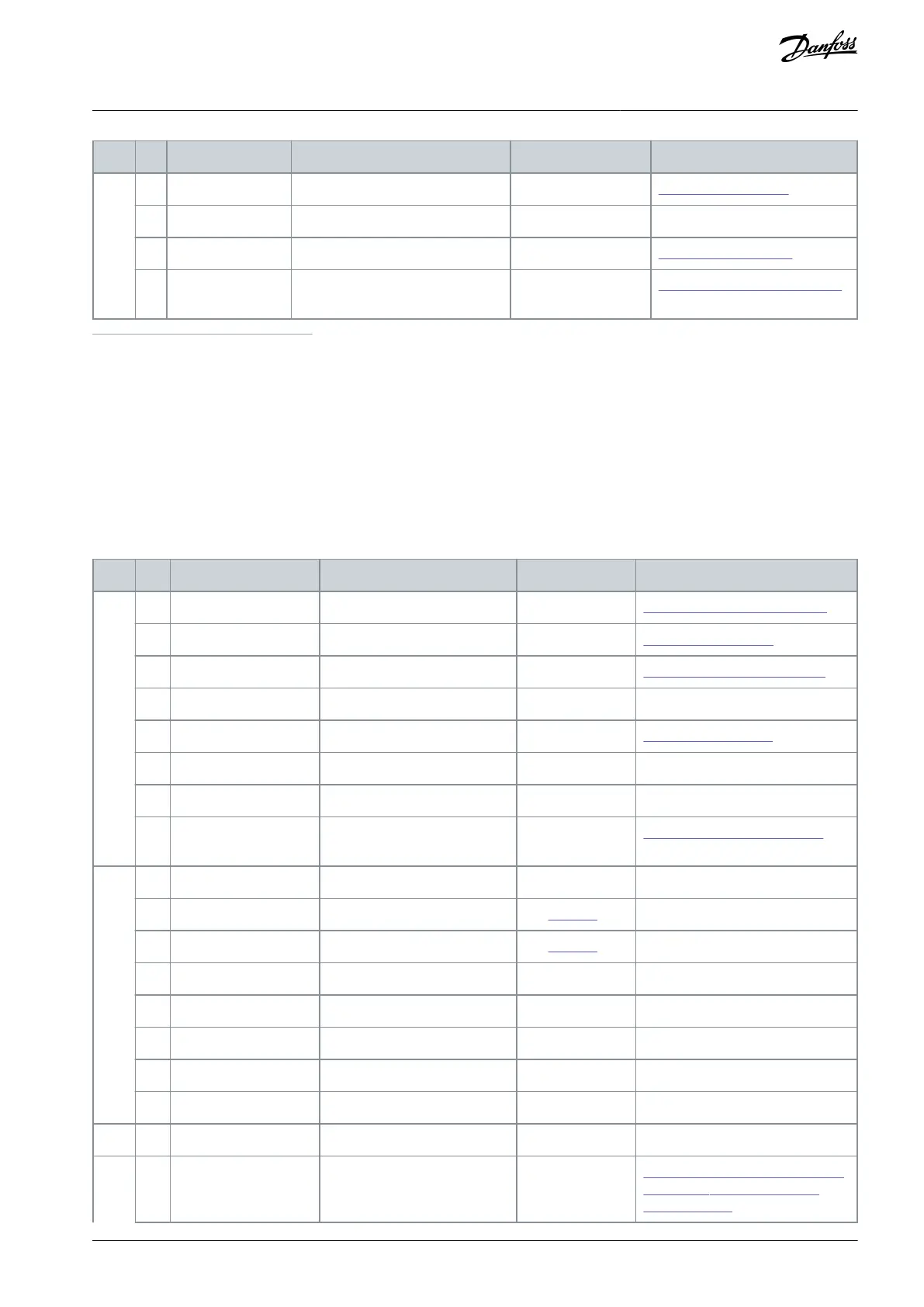
7.1.6.7 Safety Control Word 2 (S_STW2)
Compared to Safety Control Word 1, Safety Control Word 2 has two extra bytes, so Standard Telegram 31 can be used with more
safety functions than Standard Telegram 30. With these bytes, it is possible to select between 3 different SLS limits and activate
positive and negative safe direction functions. Byte 3 is identical to Byte 1 of Safety Control Word 1 (S_STW1).
Table 56: Description of Safety Control Word 2 (S_STW2)
6.2.2.4 The STO and SBC Signals
6.2.4.6 The SS2 and SOS Signals
Acknowledge safety fault buf-
fer (1->0 edge)
6.1.6 Reset of a Safety Function
Bit 0 for coding SLS limit
(1)
Bit 1 for coding SLS limit
(1)
Acknowledge safety function
(0->1 edge)
6.1.5.1 Acknowledgment of a Safe-
ty Function6.1.5.2 Start-up Ac-
knowledgment
AQ319736045637en-000101 / DPD01798 | 119Danfoss A/S © 2021.06
Safe Fieldbuses
VACON® NXP Advanced Safety Options
Operating Guide