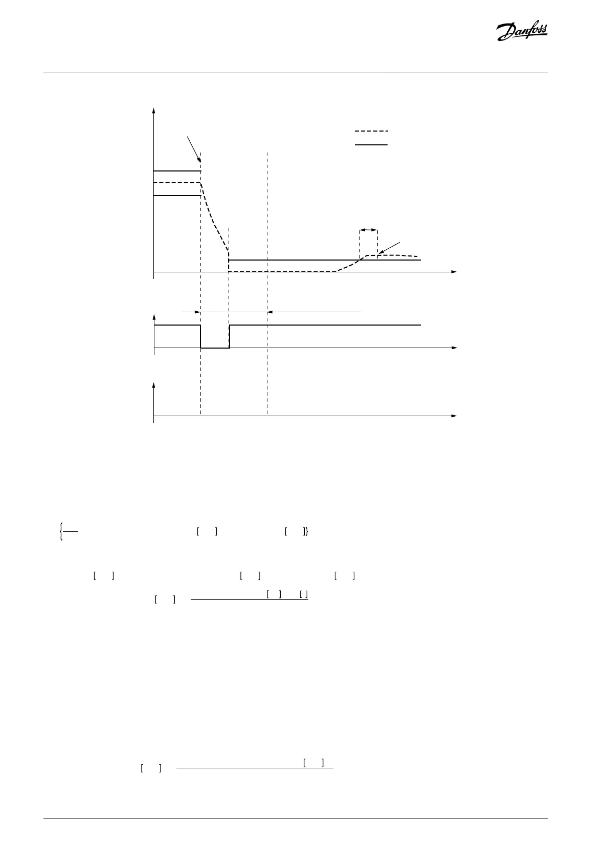
Coast Stop Time
Speed
RUN Not RUN Not RUN
Coast Stop
Drive State
Encoder Speed
Allowed Deviation
of Speed Sources
t
Reaction
Allowed error
monitoring
Speed deviation timer
e30bi374.10
Illustration 16: Estimated speed monitoring when the AC drive is not operating. A state "Not RUN" can be caused, for example, by a fault or a
stop command given to the AC drive.
To make sure that your system operates correctly and safely, set the value of Allowed Deviation of Speed Sources separately for
each application. Use this formula as a starting point to find the optimal value for the parameter. It is possible that the formula does
not give correct values with motors that have a large nominal slip, for example small motors or specially designed motors.
The Allowed Deviation of Speed Sources [rpm] =
max
5
100
×Synchronousnominalspeed rpm , 2×Nominalslip rpm
where
Nominalslip rpm = Synchronousnominalspeed rpm − Nominalspeed rpm
Synchronousnominalspeed rpm =
Nominalfrequency Hz × 60 s
polepairnumber
To make sure that the system is safe, parameters Allowed Deviation of Speed Sources and Speed Deviation Timer should be set to
the smallest possible values with which the process can operate without the comparison fault appearing too often. Setting parame-
ter Speed Deviation Timer to a greater value can give additional process availability but decrease the response time of the safety
system in fault situations.
3.6.9 Estimated Speed and Gear Systems
Set the ratio between the speed measured by a sensor and estimated speed during parameterization of the option board. Estima-
ted speed is calculated for the motor shaft. If the speed sensor is not on the motor shaft and thus measures a different speed, the
ratio between the speeds must be set with parameters Gear Ratio Divider and Gear Ratio Multiplier. The safety functions operate in
the external speed sensor speed level. In practice, the estimated speed calculated for the motor shaft is scaled to match to the exter-
nal sensor speed level.
Estimatedspeed(Actual) rpm =
Estimatedspeed(Motorshaft) rpm
Gear RatioMultiplier/Gear RatioDivider
The relation between the estimated speed and external speed sensor speed can be expressed by this formula:
AQ319736045637en-000101 / DPD0179842 | Danfoss A/S © 2021.06
Overview of the System
VACON® NXP Advanced Safety Options
Operating Guide