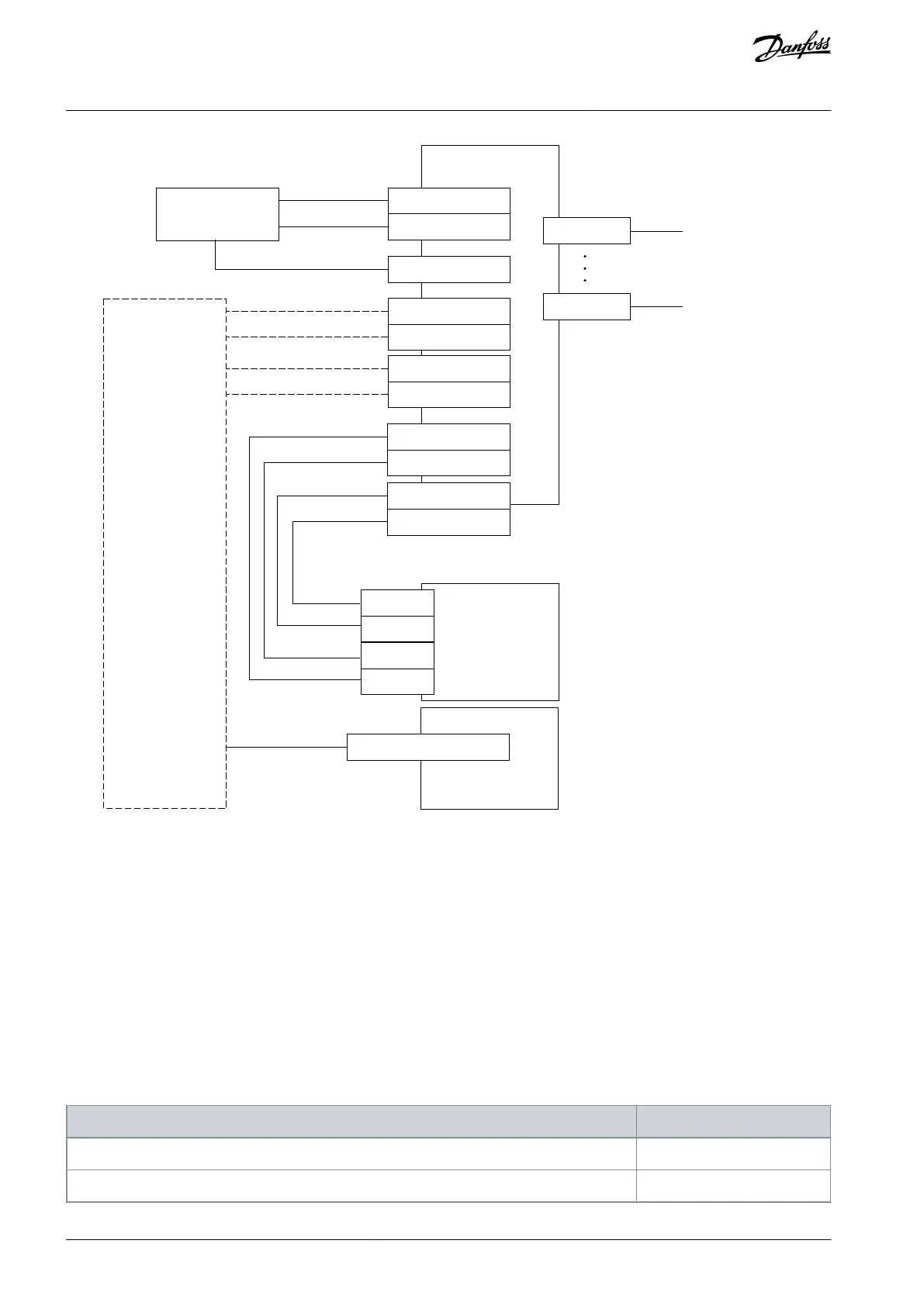
Control switch
Process
control
SLS
X4-11 (DIN1A)
X4-12 (DIN1B)
X5-1
X3-9 (+24V)
X3-5 (OUT1A)
X3-6 (OUT1B)
X3-7 (OUT2A)
X3-8 (OUT2B)
Advanced safety
option board
X5-8
Encoder input
connections
X3-1 (STO 1)
X3-2 (STO 2)
STO
option board
OPTAF
STO
X3-3 (GND)
X3-4 (GND)
SD2+
SD1+
SD2-
SD1-
Drive
Frequency reference
Illustration 81: SLS and SQS Functions with Ramp and Speed Limitation Controlled by Process Control System
13.7 Using an Output of the Option Board to Control the Access to an Area
This configuration uses the SLS function to monitor the speed of the motor and to control an external door lock with the Advanced
safety option board OPTBN. The SQS function is used as a violation response of the SLS function. The SLS function is controlled by
an external system. An external acknowledgment is used. No external safe reset is required, the drive reset is used to deactivate the
STO function and to reset the faults.
The SLS function operates in the manual acknowledgment mode with the drive acknowledgment disabled. SLS t1 is set to 5.0 s.
The SQS function is used only as violation response of the SLS function.
SLS 1 control is assigned to Digital Input 2. Digital Output 1 is used for the access control. The signal SLS 1 Reached is used to deter-
mine the state of Digital Output 1. When the signal SLS 1 Reached is active, the output is activated.
A Sin/Cos encoder is used to measure the speed of the motor shaft. External control for the speed reference to the drive is assumed
for realizing the limited speed mode.
Table 115: Configuration in the OPTBN: Used Safety Functions: SLS, SQS
Acknowledgment Mode (SLS)
AQ319736045637en-000101 / DPD01798182 | Danfoss A/S © 2021.06
Configuration Examples
VACON® NXP Advanced Safety Options
Operating Guide