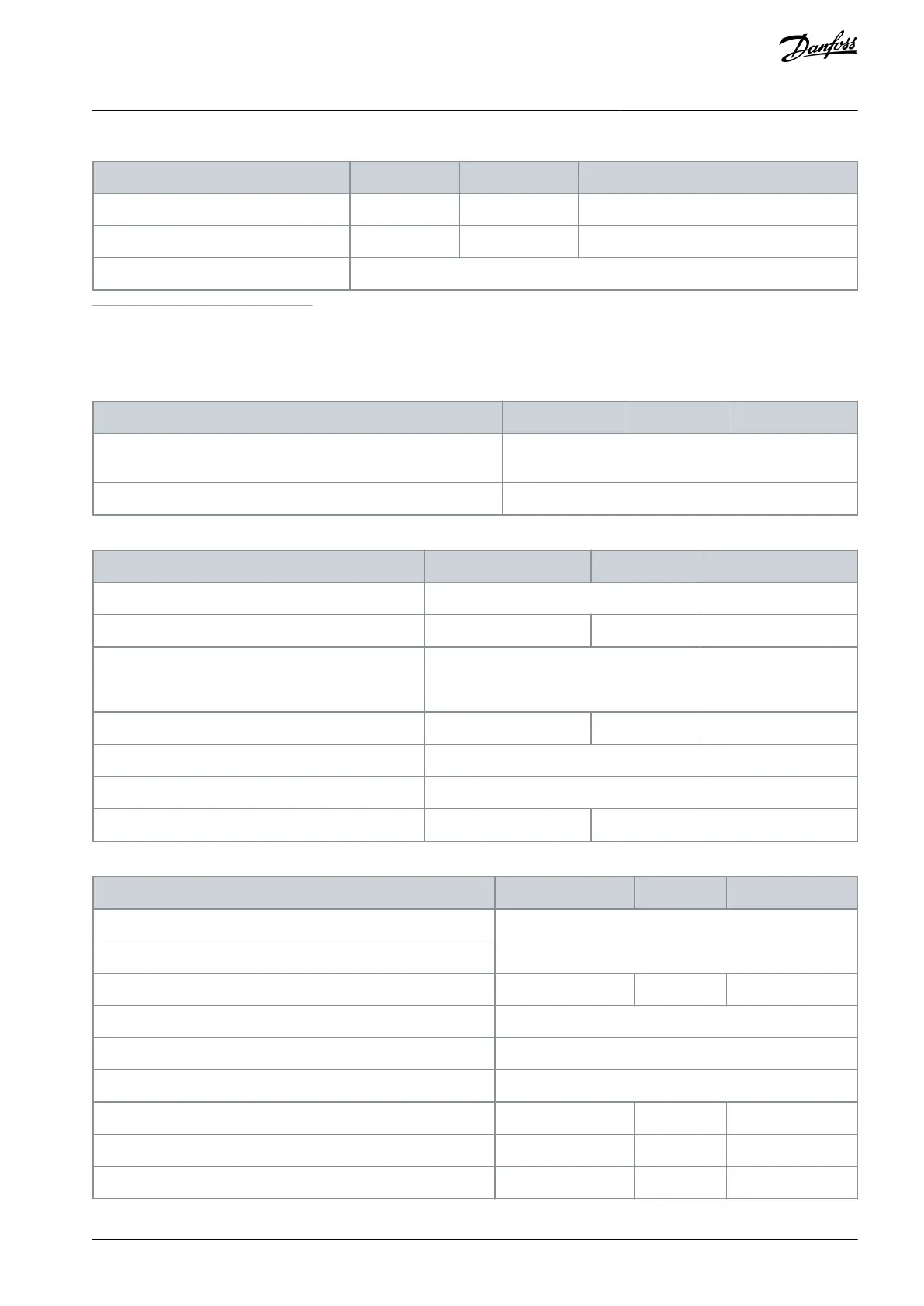
Table 91: 24 V Supply Output
Technical item or function
150 mA (250 mA combined
(1)
)
1
Combined maximum output current for the Digital Output (STO & normal) and 24V supply is 250 mA.
11.3 Speed Measurement Data
Table 92: Multiple Speed Source Cross-comparison
Technical item or function
Allowed deviation between speed sources (encoder/proximity sen-
sor/ estimated speed)
Set with parameter Allowed Deviation of Estimated Speed.
Allowed time for exceeding the allowed speed deviation
Set with parameter Allowed Deviation Timer.
Table 93: Sin/Cos
Technical item or function
5 V, 12 V, 15 V, 24 V. ± 5%
Operating Sin/Cos waveform
1 Vpp ± 25% with +2.5 VDC offset
Operating phase-shift Sin/Cos
sin
2
x + cos
2
x = 1 ± 40%
See recommendation of encoder manufacturer.
Conductor size/cross-section (AWG)
Table 94: Digital Pulse
Technical item or function
Encoder Supply Voltage HTL
5 V, 12 V, 15 V, 24 V. ± 5%
Encoder Supply Voltage TTL
5 V, 12 V, 15 V, 24 V. ± 5%
According to RS-422 interface standard
Differential Input Voltage HTL(Active, logic 1) VA→Ā
Differential Input Voltage HTL(Inactive, logic 0) VA→Ā
Operating phase-shift A/B
AQ319736045637en-000101 / DPD01798 | 147Danfoss A/S © 2021.06
Technical Data
VACON® NXP Advanced Safety Options
Operating Guide