0 = Ramp1, 1 = Ramp2, for SS1
and SS2
6.1.7 Ramps6.2.3.5 The SS1 Sig-
nals6.2.4.6 The SS2 and SOS Signals
1
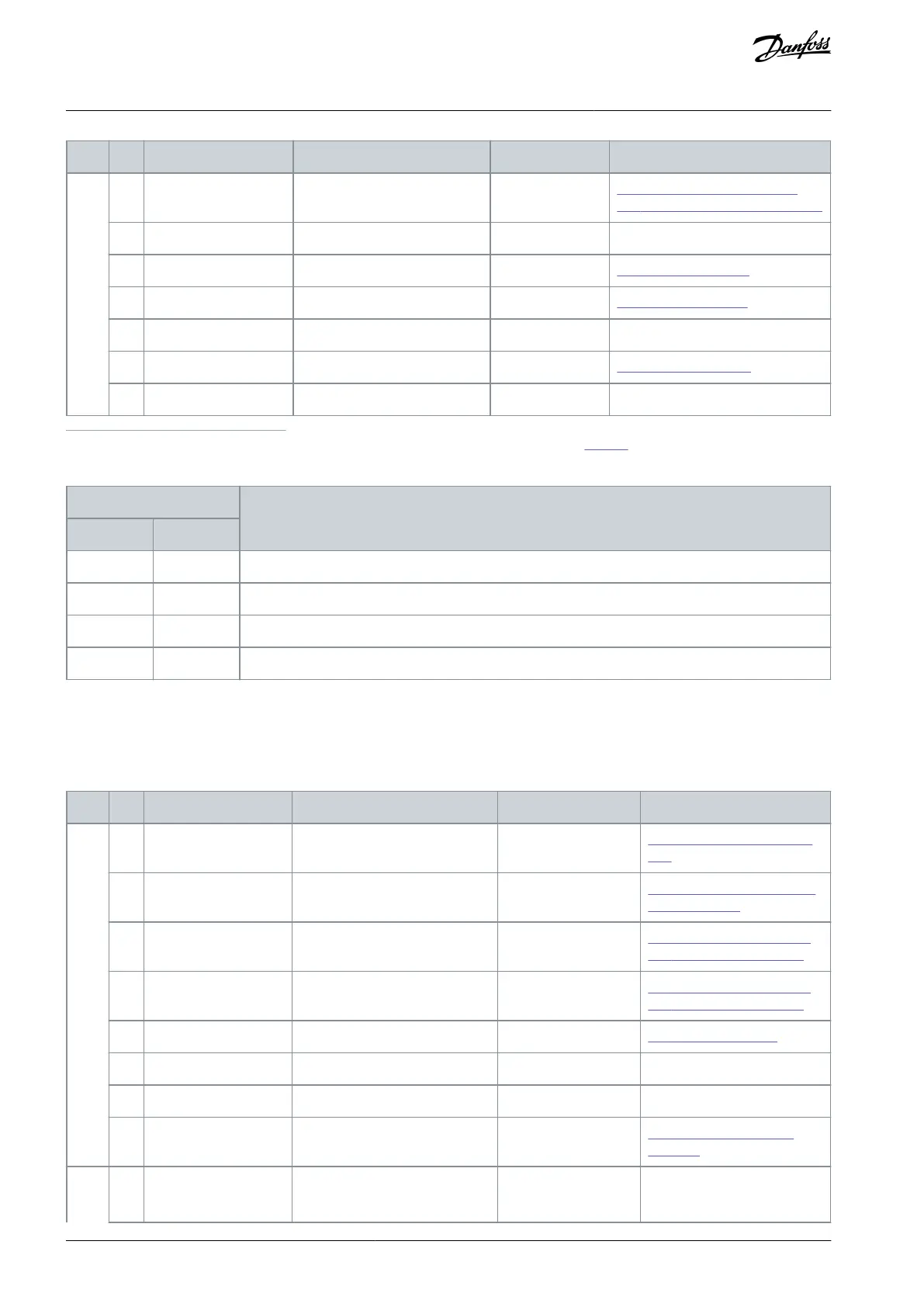
The actual selection for the monitoring limit is made with SLS_LIMIT_BIT0 and SLS_LIMIT_BIT1. See Table 57.
Table 57: SLS Limit Selection
SLS 1 Limit is selected when SLS (Byte 0, bit 4) is set to 0.
SLS 2 Limit is selected when SLS (Byte 0, bit 4) is set to 0.
SLS 3 Limit is selected when SLS (Byte 0, bit 4) is set to 0.
No SLS limit requested. SLS (Byte 0, bit 4) must be set to 1.
7.1.6.8 Safety Status Word 2 (S_ZSW2)
Safety Status Word 2 is used together with Safety Control Word 2 (S_STW2) to form Standard Telegram 31. Compared to Safety
Status Word 1, Safety Status Word 2 has multiple SLS limits and the SSM function status.
Table 58: Description of Safety Status Word 2 (S_ZSW2)
Safe Torque activated and tor-
que removed from drive
6.2.2.4 The STO and SBC Sig-
nals
SS1 Active or SQS Ac-
tive
6.2.3.5 The SS1 Signals6.2.5.3
The SQS Signals
SS2 Active or SQS Ac-
tive
6.2.4.6 The SS2 and SOS Sig-
nals6.2.5.3 The SQS Signals
Safe Operating Stop activated
6.2.4.6 The SS2 and SOS Sig-
nals6.2.5.3 The SQS Signals
Safe Limited Speed activated
(2)
Drive Safety Process fault status
6.1.4 Violation of a Safety
Function
AQ319736045637en-000101 / DPD01798120 | Danfoss A/S © 2021.06
Safe Fieldbuses
VACON® NXP Advanced Safety Options
Operating Guide