Table 12: Termination Resistor Usage
Encoder signal loop-back used
Termination resistor on the Advanced safety option board used
Use of a termination resistor is not required
3.6.5 Proximity sensors
It is possible to connect two proximity sensors to the safe I/O of the Advanced safety option board. The option board supports only
the 4-wire PNP type proximity sensors. A proximity sensor must supply two signals, a normal and an inverted signal, to the Ad-
vanced safety option board.
When one proximity sensor is used, connect it to the digital input 1 of the safe I/O. If a second proximity sensor is added, connect it
to the digital input 2. The two proximity sensors must be installed so that they have the same number of pulses per rotation.
For a proximity sensor connection example, see 13.9 A Proximity Sensor for Speed Measurement.
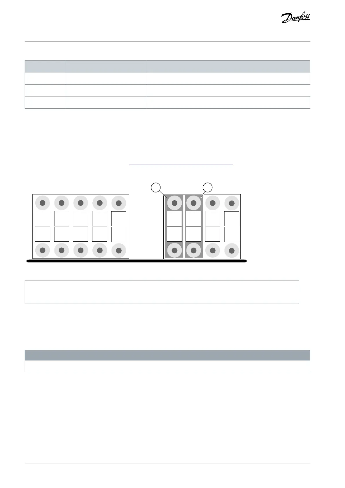
Illustration 14: Connecting Proximity Sensors to the Connectors of the Option Board
Terminals for the first proximity sensor
Terminals for the second proximity sensor
The duty cycle (that is, the active-inactive signal ratio) of the proximity sensors is set during the parameterization. Setting the duty
cycle to a value other than 50% (1:1 signal ratio) decreases the supported maximum frequency of the proximity sensor signals. The
Advanced safety option board does not monitor that the actual duty cycle corresponds to the parametrized value. The duty cycle
must be set to an approximately correct value so that the Advanced safety option board can correctly detect when the speed ex-
ceeds the supported maximum frequency and trigger a fault. Otherwise the short pulses at high speed may not be detected and the
speed measurement may indicate too low a speed.
N O T I C E
Use of ramp monitoring is not recommended when only proximity sensors are used as speed sensor.
Due to the way the speed is calculated, it is not recommended to set the safety function speed limits below a certain value. This
value depends on the pulses per revolution of the proximity sensor signal. A formula for calculation of the rpm value is 15000/ppr.
AQ319736045637en-000101 / DPD0179838 | Danfoss A/S © 2021.06
Overview of the System
VACON® NXP Advanced Safety Options
Operating Guide