Table 9: Example 3
Result of the logical function
SLS 1 Reached = 0
SSM Below Min Limit = 0
SLS 1 Reached = 0
SSM Below Min Limit = 1
or
SLS 1 Reached = 1
SSM Below Min Limit = 0
SLS 1 Reached = 1
SSM Below Min Limit = 1
EXAMPLE 4 (USING GROUP 2):
Selected signals: SLS 1 Reached, SSM Below Min Limit
Logical function: NAND
Table 10: Example 4
Result of the logical function
SLS 1 Reached = 0
SSM Below Min Limit = 0
SLS 1 Reached = 0
SSM Below Min Limit = 1
or
SLS 1 Reached = 1
SSM Below Min Limit = 0
SLS 1 Reached = 1
SSM Below Min Limit = 1
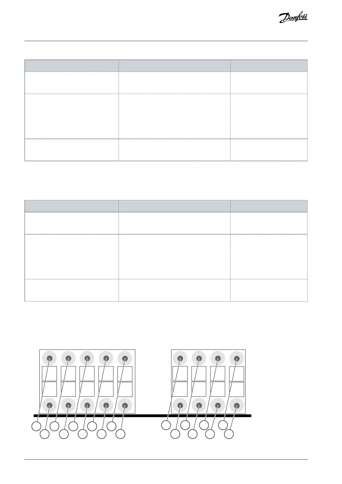
3.5.4 Option Board OPTBL
Use the Advanced safety option board OPTBL when no encoder is used to measure the speed of the motor shaft.
1 3 5 7 9
2 4 6 8
11 13 15 17
12
14 16 1810
Dout1 Dout2 Din1 Din2 Din3 Din4
X4
X3
e30bi410.10
Illustration 7: The Terminals X3 and X4 of the OPTBL Option Board
AQ319736045637en-000101 / DPD0179830 | Danfoss A/S © 2021.06
Overview of the System
VACON® NXP Advanced Safety Options
Operating Guide