Table 6: The Available Signals in Configuration Groups
STO Reached
SS1 Reached
SS2 Reached
SQS Reached
SOS Reached
SBC Reached
STO and SBC Reached
SLS 1 Reached
SLS 2 Reached
SLS 3 Reached
SSR Reached
SMS Reached
SSM Reached
SSM Above Max Limit
SSM Below Min Limit
STO Active
SS1 Active
SS2 Active
SQS Active
SLS 1 Active
SLS 2 Active
SLS 3 Active
SSR Active
SMS Active
SSM Active
Warning in any safety function
Limit violation fault in any safety function
During operation, the option board uses the selected signals and applies the selected logical function to determine the state of the
output. If the result of the logical function on the actual state of the selected signals is "true", the output is active. If the result is
"false", the output is inactive.
EXAMPLE 1 (USING GROUP 2):
Selected signals: SLS 1 Reached, SSM Below Min Limit
Logical function: OR
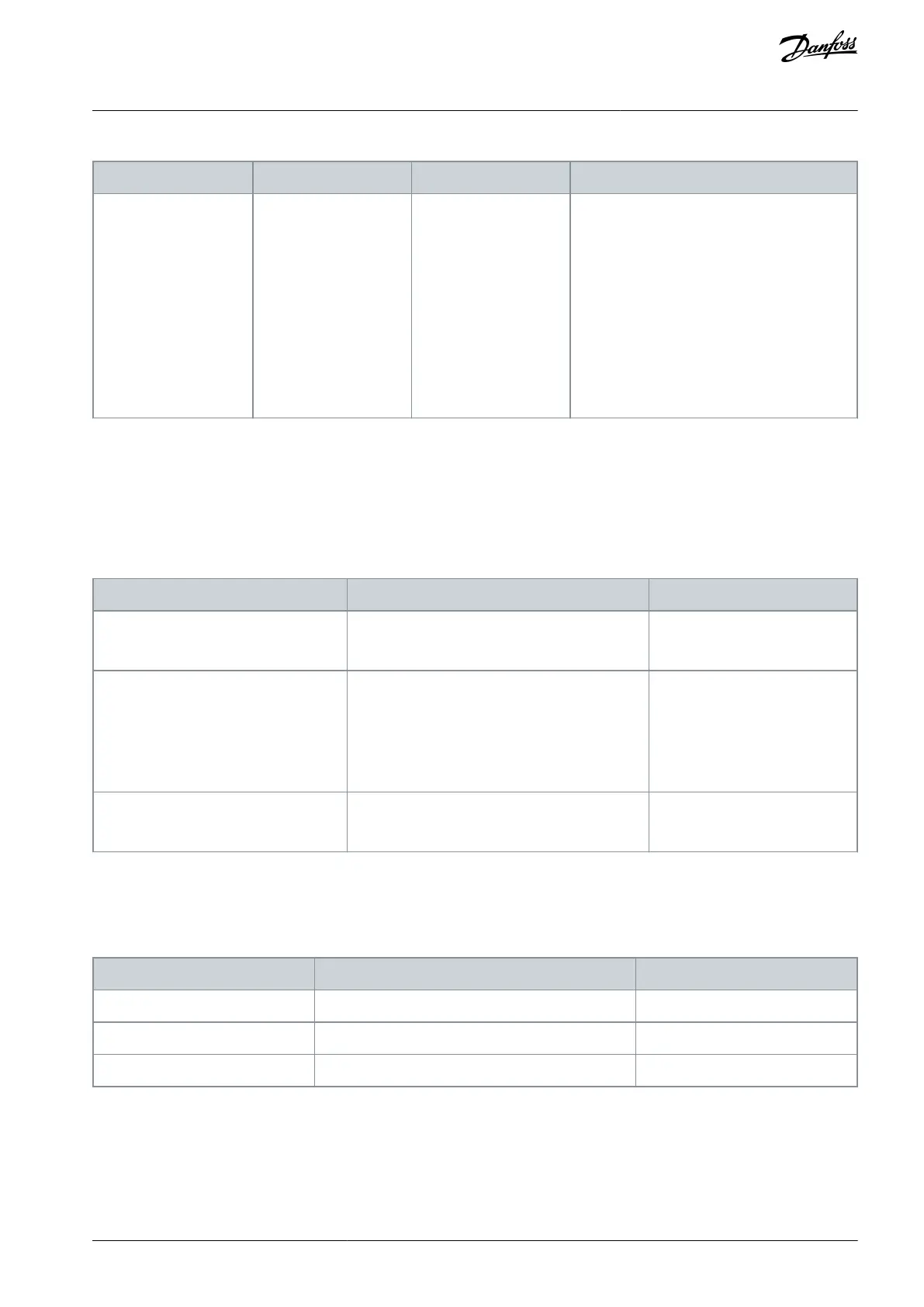
Table 7: Example 1
Result of the logical function
SLS 1 Reached = 0
SSM Below Min Limit = 0
SLS 1 Reached = 0
SSM Below Min Limit = 1
or
SLS 1 Reached = 1
SSM Below Min Limit = 0
SLS 1 Reached = 1
SSM Below Min Limit = 1
EXAMPLE 2 (USING GROUP 2):
Selected signals: SLS 1 Reached
Logical function: NOR
Table 8: Example 2
Result of the logical function
EXAMPLE 3 (USING GROUP 2):
Selected signals: SLS 1 Reached, SSM Below Min Limit
Logical function: AND
AQ319736045637en-000101 / DPD01798 | 29Danfoss A/S © 2021.06
Overview of the System
VACON® NXP Advanced Safety Options
Operating Guide