When you use the safety-aware Multipurpose drive application, the SS1 function is realized by the drive application when the SS1
function is requested from the Advanced safety option board. The ramp definitions for the controlled ramp are taken from drive
ramp 1.
The SLS speed limit is realized by the drive application when the SLS function is requested from the Advanced safety option board.
The speed limit is taken from the Advanced safety option board. The drive application limits the speed to 95% of the parameterized
limit. Ramping below the speed limit is realized using drive ramp 1.
Table 129: Configuration in Safety-aware Multipurpose Drive Application
P2.1.4 Deceleration Time 1
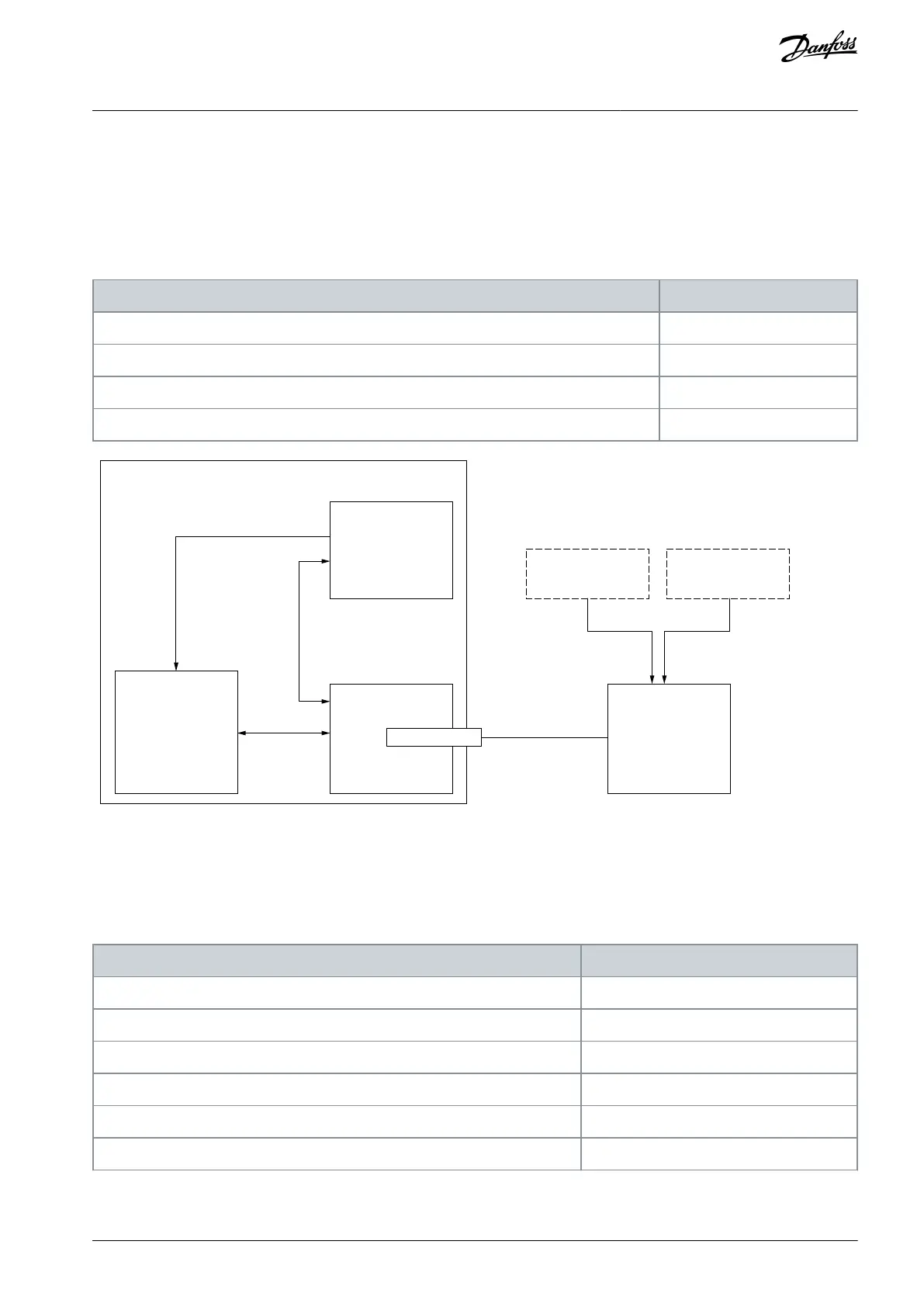
AC drive
PROFIdrive
over
PROFIsafe
compatible
drive
application
OPTE5
(Slot E)
Safety PLC
Sensory
device
Stop
switch(es)
Advanced
safety option
board
PROFIsafe
over PROFIBUS
PROFIsafe
(Drive internal
communication)
9-pin DSUB
Safety function states
Illustration 83: Realizing PROFIdrive over PROFIsafe
13.9 A Proximity Sensor for Speed Measurement
This is a configuration for one proximity sensor with the Advanced safety option board OPTBL. No safety functions are included in
this example. A proximity sensor with 16 pulses per rotation and an ACTIVE-INACTIVE signal duty cycle of 1:1 is used.
Table 130: Configuration in the OPTBL Option Board: Used Safety Functions: Not Considered.
Speed measurement configuration
Proximity Sensor Number of Pulses
Proximity Sensor Duty Cycle
AQ319736045637en-000101 / DPD01798 | 187Danfoss A/S © 2021.06
Configuration Examples
VACON® NXP Advanced Safety Options
Operating Guide