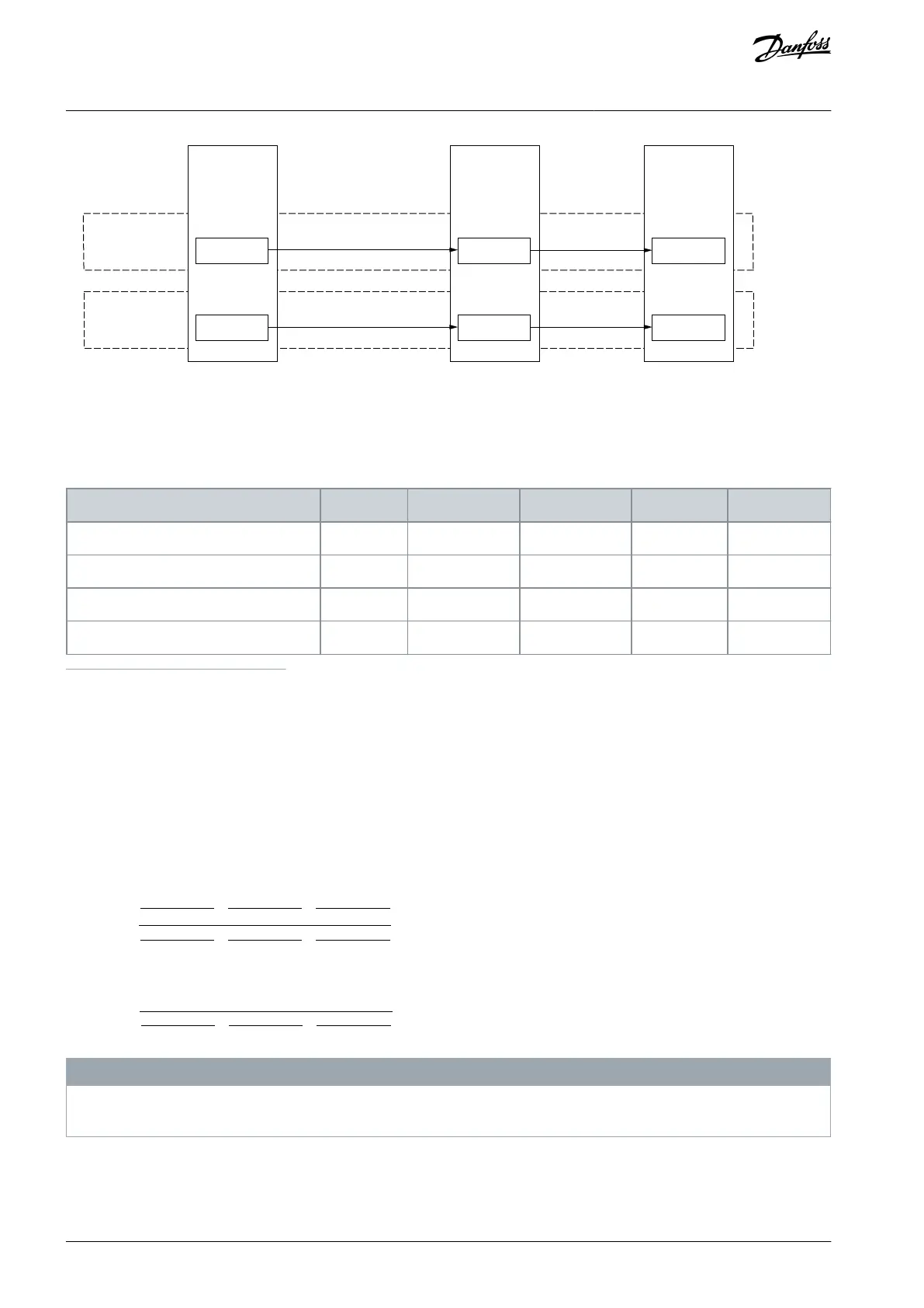
Emergency
stop switch
(SIL3,
PLe)
OPTBL
(SIL3, PLe,
Cat 4)
OPTAF &
AC drive
(SIL3, PLe,
Cat 3)
Stop (STO) request
Stop (STO) request
STO
STO
Channel 1
Channel 2
Illustration 5: A Logical Presentation of the STO Safety Function
In this example case, the STO function has one activation per day, and a lifetime of 20 years. For the emergency stop switch, β = 10%
is used as the susceptibility to common cause failure between the channels. No proof test is executed during the lifetime. The exam-
ple system is limited to Category 3 because the Category 3 element OPTAF option board is used as a single final element.
Table 3: An Example of System Level Calculations for the STO Safety Function
Overall safety system (for STO)
1
This value is calculated directly from the values provided by the manufacturer. The diagnostic capabilities of OPTBL have not been taken into ac-
count. The calculation formula: PFH
d
= (1- β)
2
x λ
ch1
x λ
ch2
x T
1
+ β x (λ
ch1
+ λ
ch2
)/2, where λ
ch
= (0.1 x cycles per hour) / B10
d
).
2
The calculation formula: PFD
avg
= (PFH
d
x T
M
)/2.
3
The OPTBL executes "Cross monitoring of inputs without dynamic test", DC: 0%...99%, depending on how often a signal change is done by the
application. A DC of 90% is assumed with the once a day activation.
4
The calculation formula: MTTF
d
= B10
d
/ (0.1 x cycles per year).
5
OPTAF manual: DC
avg
= low, using the lower end of the possible range (60%...90%)
6
Sum of the individual PFH
d
values.
7
Sum of the individual PFH
avg
values.
8
The calculation formula:
DC
avgSTO
=
DC
Switch
MTTF
dSwitch
+
DC
OPTBL
MTTF
dOPTBL
+
DC
OPTAF
MTTF
dOPTAF
1
MTTF
dSwitch
+
1
MTTF
dOPTBL
+
1
MTTF
dOPTAF
9
According to EN ISO 13849-1, the MTTF
d
must be limited to a maximum limit of 100 years per channel. The calculation formula:
MTTF
dSTO
=
1
1
MTTF
dSwitch
+
1
MTTF
dOPTBL
+
1
MTTF
dOPTAF
N O T I C E
When designing systems according to IEC-61508, the requirement for the value of the Safe Failure Fraction (SFF) is considered on
subsystem level, not on system level.
AQ319736045637en-000101 / DPD0179826 | Danfoss A/S © 2021.06
Overview of the System
VACON® NXP Advanced Safety Options
Operating Guide