1. Introduction
UniSite-xpi User Manual 1-3
UniSite-xpi External Features
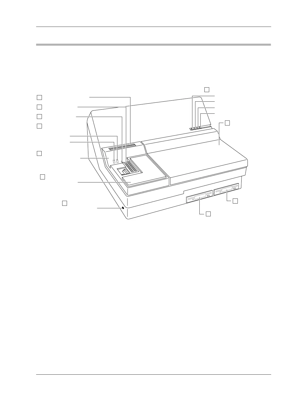
The Front Panel The front panel features of UniSite-xpi are shown in Figure 1-2.
1. Disk Storage Slots—A convenient place to store two data disks.
2. Device Socket—Holds the device to be programmed or the master
device to be read.
3. Socket Lever—Locks the device into the device socket.
4. Module Status Indicators—Provide information about the
operational status of the module.
a) ACTIVE Indicator—This lamp is lit when a device-related
operation is in progress.
b) READY Indicator—This lamp is lit when the device socket is
ready to accept a device.
5. Conductive Foam—Provides a convenient, safe place to store static-
sensitive devices while using UniSite-xpi.
6. Ground Connection—Connect an antistatic wrist strap here.
7. Drive A—The main disk drive. Insert the System disk here.
8. Drive B—The auxiliary disk drive. Insert an Algorithm disk here.
Figure 1-2
Front Panel Features
0047-3
a. POWER
b. TERMINAL PORT
c. REMOTE PORT
d. SELF TEST
UNISITE STATUS INDICATORS
9
1
2
3
4
5
6 GROUND
CONNECTION
8
7
DRIVE B
DRIVE A
SOCKET LEVER
MODULE STATUS
INDICATORS
a. READY
b. ACTIVE
CONDUCTIVE FOAM
(Device Storage)
DEVICE SOCKET
DISK STORAGE SLOTS
(PSM) PACKAGE-
SPECIFIC MODULE
(FSM) FUNCTION-
SPECIFIC MODULE
10
11
 Loading...