A. Using Modules
UniSite-xpi User Manual A-7
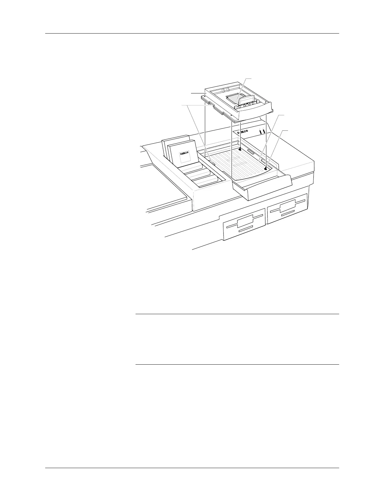
4. Align the notches on the Base with the notches in the opening, as
shown in Figure A-5.
5. Line up the four guide pins in the Base opening with the holes in the
Base, and insert the Base into the opening.
6. Finally, squeeze the Base and module handles together, locking the
Base into place. You do not need to use excessive force when
compressing the handles.
CAUTION: You can damage PinSite by squeezing too hard on the
handles.
Conductive Pad The conductive pad, shown in Figure A-5, is required to complete the
electrical connection between the programmable device pins and the
Base’s circuit board.
CAUTION: Do not remove this conductive pad unless you are cleaning
or replacing it.
See page A-20 for more information on conductive pad care and
replacement procedures.
Figure A-5
Aligning the Base
ACTIVE
READY
PINSITE
44 Pin PLCC
44 Pin PLCC
0564-3
GUIDE PIN
(1 OF 4 )
BASE RECEPTACLE
OPENING
ELASTOMERIC CONDUCTIVE PAD
DO NOT REMOVE
ALIGN NOTCHES
BASE