TWO-HEAD DIMENSIONING SYSTEM REFERENCE MANUAL
6. Adjust the three following parameters in the DM3610 User Interface for each
dimensioner in Modify Settings | Dimensioning | Calibration:
Set Scan Points to 900 (default) unless authorized by Datalogic.
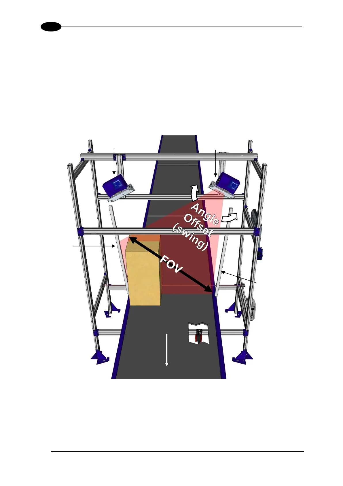
Field of View: Adjust FOV to cover largest system boxes at edges of conveyor.
Angle Offset: Adjust the Angle Offset to cover largest system boxes at edges of
conveyor. In order to achieve a satisfactory calibration, you will need to go back
and forth between the Field of View and Angle Offset parameters making single
integer adjustments.
Figure 53: Field of View (FOV) and Angle Offset
The laser line on the near side must hit the very edge of the dimensioning area, and the laser
line on the far side should cover the entire top of the box and extend from 25mm [1-inch] to
50mm [2-inches] beyond the top outside edge of the box. The laser beam on the opposite
side of the belt must be completely caught by the beam catcher.


 To Next Page