TWO-HEAD DIMENSIONING SYSTEM REFERENCE MANUAL
3.9 PHOTOELECTRIC SENSOR CONNECTIONS
Multi–head dimensioning applications may use a Datalogic photoelectric sensor as a trigger
device. The photoelectric sensor is only required if dimension data is transmitted at a certain
transmit point. The photoelectric sensor is wired directly into the CBX510.
If your application uses a trigger other than the one specified by Datalogic, follow the
appropriate wiring diagram to assure proper wiring.
IMPORTANT: You must use shielded interface cables with this product.
To maintain FCC compliance, the cable shield must make a 360-degree
connection to the shielded mating connector.
NOTE: To confirm the photoelectric sensor is functioning properly, watch
the TRIG LED while the photoelectric sensor’s beam is blocked. The
Datalogic photoelectric sensor also includes a status LED.
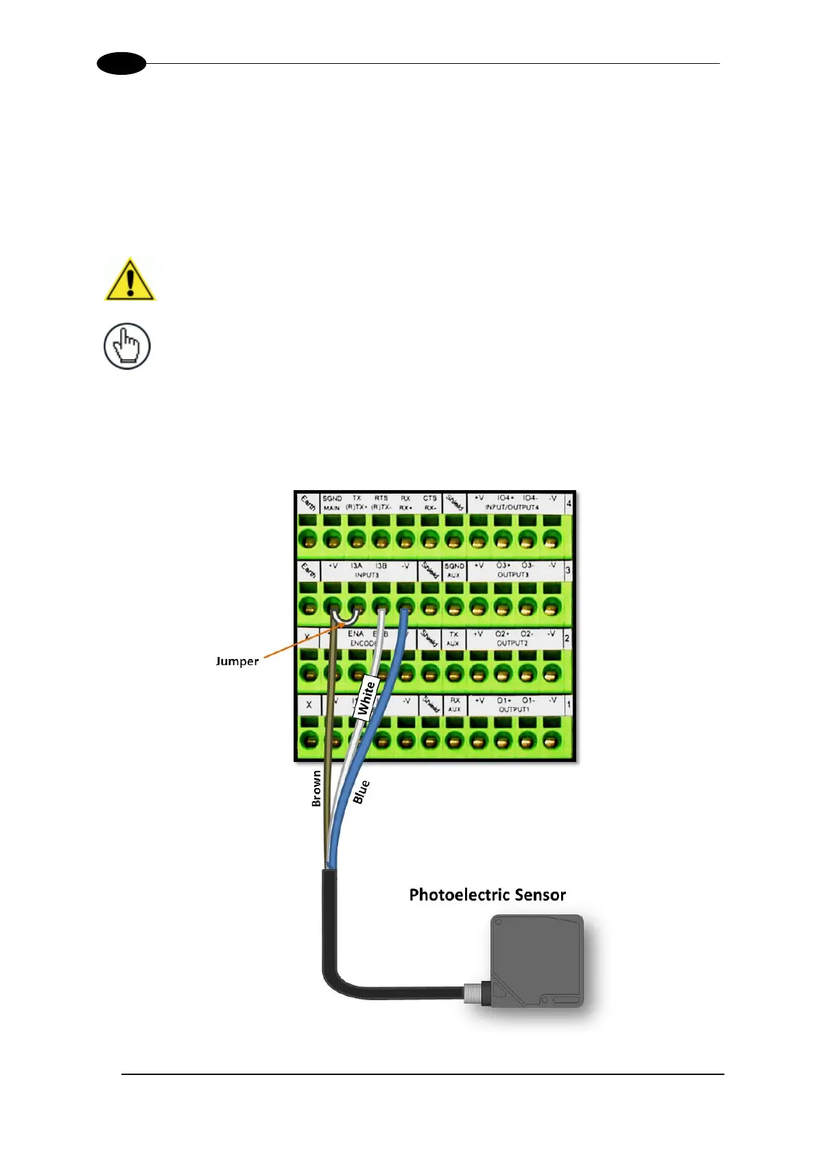
The following diagram illustrates standard/recommended wiring of the Photoelectric Sensor
to the CBX510.
3.9.1 Photoelectric Sensor (NPN)
Figure 38: Photoelectric Sensor Wiring (NPN Output)