TWO-HEAD DIMENSIONING SYSTEM REFERENCE MANUAL
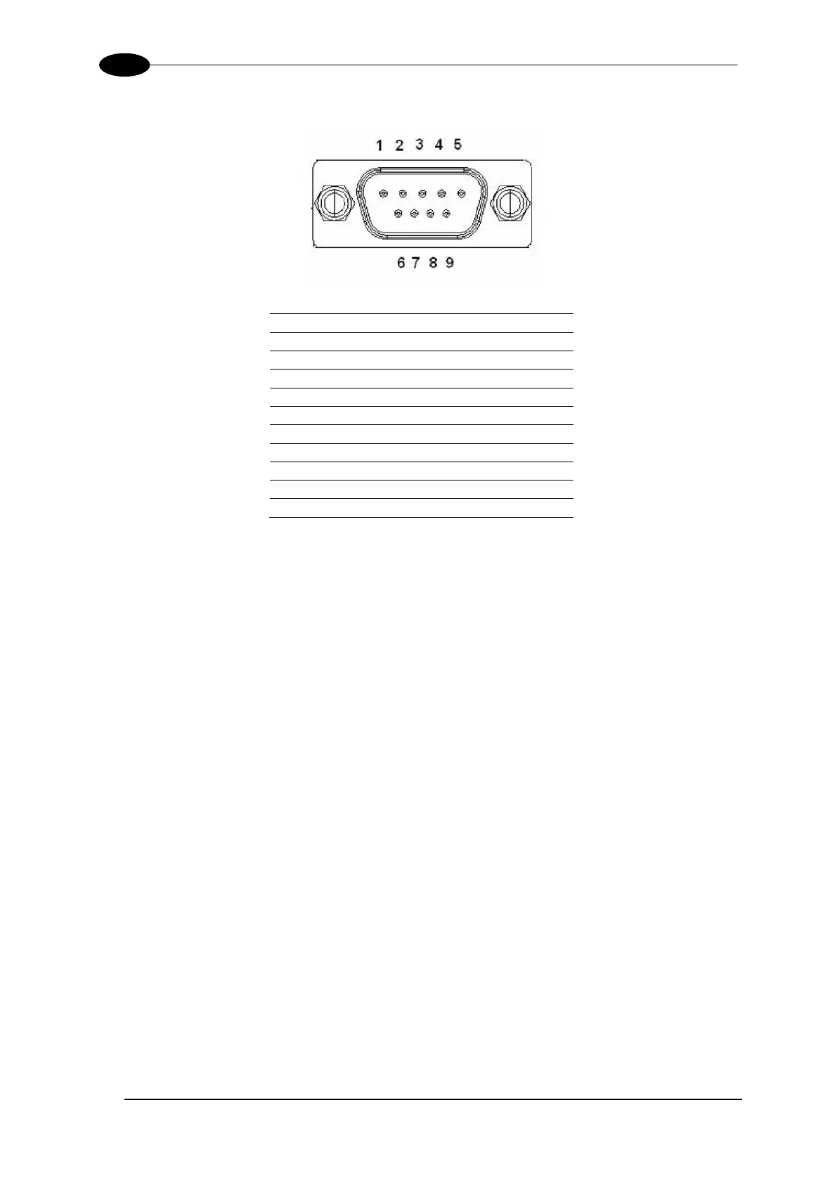
Pin outs:
*NC represents “No Connection”.
RS232 provides point-to-point communications at distances up to 15 meters [50 feet].
RS422 provides point-to-point communications at distances up to 1200 meters [3940
feet]
3.15 CHECKING THE INSTALLATION
After completing the installation of your two-head dimensioning system:
Confirm that the dimensioners, DC3000 Controller, and CBX510 have been properly
installed mechanically and electrically. Use the Installation Sequence at the beginning
of this chapter and your application specifications to check your installation.
All interconnections should match the application drawings. (Any block diagrams or
wiring diagrams provided in this manual are superseded by any customer-specific
documentation provided by Datalogic.)
The next step is to configure the parameters to meet the needs of your application.
Details on using the DC3000 User Interface (Controller) are provided in chapter 4.