Removal and Replacement
4-8
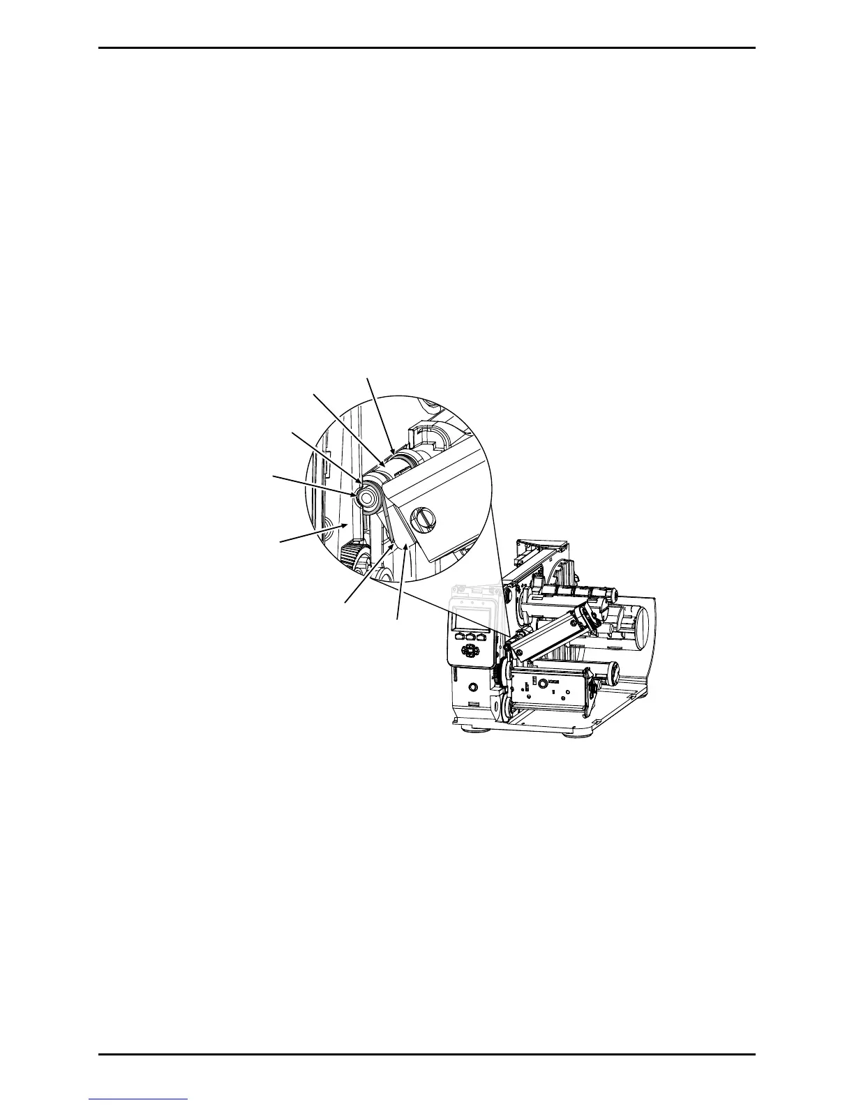
Installation:
1. Place the Rear Lift Spring (short leg toward the Centerplate) onto the shoulder of the
Platen Block Hinge then lower the Printhead Assembly until aligned with the Plate Block
Hinge.
2. Place the Front Lift Spring (bent leg to captivate the Printhead Assembly) inline, against
the Printhead Assembly, then insert the Pivot Pin (solid end forward). Raise the
assembly and position the Front Lift Spring leg.
Printhead
Assembly
Pivot Pin
Platen
Block Hinge
Front
Lift Spring
Centerplate
Rear
Lift Spring
leg
3. Install and secure the Pivot Pin Screw. Test the Printhead Assembly for proper
movement and lift.
4. Attach the Drive Gear and Idler Post to the Centerplate with the Drive Gear Screw.
5. Carefully route the printhead cables through the Guard and then install the Printhead;
see Section 4.3.
6. Install the Front Cover (see Section 4.2) and the Side Cover Assembly (see Section 4.1).

 Loading...