Chapter 6 Description of Operations
PAGE 6-43
(1) Unit Information 1
SYS.000 Torque Unit Cannot be changed.
All fastening parameters within the Unit will have the same torque unit.
SYS.001 Software Version Cannot be changed.
This is the software version of the Unit.
SYS.002 Amplifier Version Cannot be changed.
This is the amplifier version.
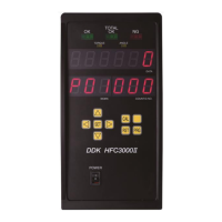
SYS.003 System Indication Cannot be changed.
This indicates whether the Unit is a multi system or a single system.
The handheld tool operates only in the single system setting.
SYS.004 External Gear Ratio Setting range: 0.300 ~ 3.000, standard setting: 1.000
When a gear is installed at the top of the tool, the gear ratio with respect to the output
shaft of the tool is set here.
Do not use a value other than 1.000 as long as an external offset gear is not used.
SYS.005 / 006 For adjustment by the manufacturer Cannot be changed.
Not used.
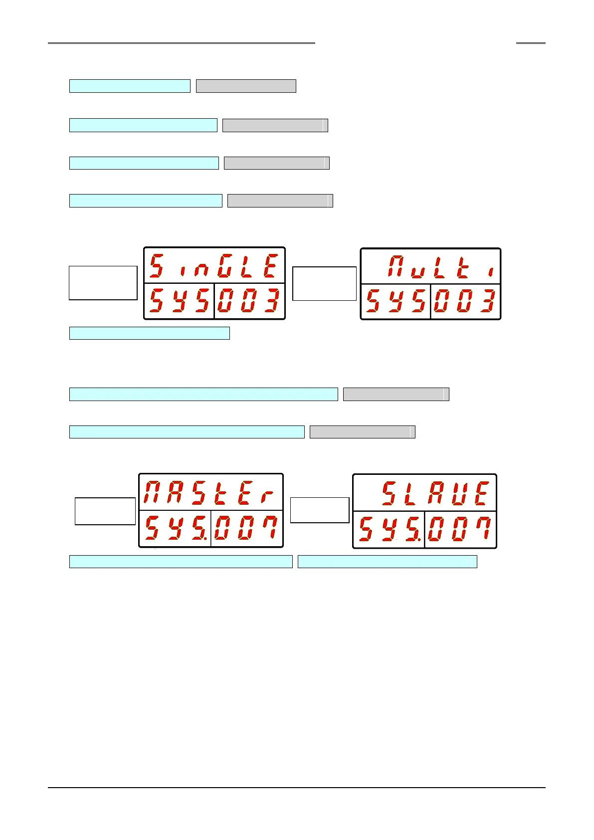
SYS.007 Communication Spindle Indication Cannot be changed.
This indicates whether the Unit is the MASTER Spindle for (PC) communication and I/O
(PLC) communication or is a SLAVE Spindle.
SYS.008 Spindle Cycle Count (×1 million) SYS.009 Spindle Cycle Count (×1)
These indicate the count at which the Unit performed the fastening operation.
* When the count is less than 1 million times, [------] is indicated for D-No. 008.
S0140185-H
 Loading...