
C
Connie JonesAug 2, 2025
What to do if DDK Power Tool shows a Setting Data Error?
- AAlyssa OconnorAug 3, 2025
If your DDK Power Tool displays a Setting Data Error, re-enter the correct setting data.
What to do if DDK Power Tool shows a Setting Data Error?
If your DDK Power Tool displays a Setting Data Error, re-enter the correct setting data.
What to do if my DDK Power Tool displays a TOOL ID Error?
If your DDK Power Tool is showing a TOOL ID Error, check the TOOL ID and ensure it matches the device specifications.
What to do if DDK Power Tool has Servo Amplifier Error?
If your DDK Power Tool is showing a Servo Amplifier Error, check the amplifier settings and connections.
What to do if DDK Power Tool displays System Memory Error?
If your DDK Power Tool displays a System Memory Error, perform a system reset and check memory components.
What to do if DDK Power Tool displays Servo Type Error?
If your DDK Power Tool displays a Servo Type Error, verify the installed servo type is correct for the unit.
What to do if DDK Power Tool displays Servo Reply Error?
If your DDK Power Tool displays a Servo Reply Error, inspect the servo connections and ensure proper functionality.
Essential safety guidelines for operating the equipment and protecting personnel.
Checklist for confirming correct model, parts, and checking for transport damage.
Outlines the warranty period, scope of coverage, and conditions for service.
Guidelines for safely transporting and storing the equipment under specific environmental conditions.
Instructions and precautions for safely installing and wiring the equipment correctly.
Guidelines and warnings for safe operation, adjustment, and parameter settings.
Explains manual structure and guidance on how to use the instruction manual.
Details the key features and capabilities of the Handheld Nutrunner.
Provides instructions for safe tool handling, installation, and environment.
Lists operational parameters like power source, installation, and operating conditions.
Details technical performance metrics like torque precision and data communication.
Explains the controller unit model naming convention.
Outlines the main functionalities of the system, including fastening and self-check.
Identifies and describes the components of the controller unit's front and bottom panels.
Describes the Angle Tool and Pistol Tool, including their components and operation.
Outlines the step-by-step process for installing the Hand System.
Provides physical dimensions and mounting guidelines for the controller unit.
Details how to connect the dedicated power cable to the unit.
Specifies the types and lengths of tool cables used for connection.
Explains the connection of external control signals via terminal blocks.
Details output signals for external monitoring devices like torque and angle.
Covers RS232C communication specifications and data format.
Explains the TCP/IP Ethernet port settings for PC communication.
Lists critical checks before powering on the equipment.
Details indicators and safety precautions during equipment activation.
Guides on inputting necessary data for fastening after activation.
Outlines post-activation checks for ZERO value, CAL value, rotation, and reverse rotation.
Explains the controller's operation and check switches, indication LEDs.
Describes the pistol-type tool, including starting switch, reversing switch, and LEDs.
Details how to switch between operation and setting modes.
Explains indications and mode changes within the RUN mode.
Covers changing modes and indications within the PROGRAM mode for parameter settings.
Describes procedures for copying parameters and erasing stored data.
Explains how to interpret NG indications and causes of failure.
Details how speed and time parameters are set for fastening operations.
Outlines the organization of system and fastening parameters.
Lists abnormal states indicated on the display and their types.
Provides detailed causes and recovery steps for various system errors.
Explains how to confirm REJECT contents and reasons for stopping.
Offers troubleshooting steps for Ethernet communication issues.
Details procedures for changing the unit's date and time settings.
Covers summary, selection criteria, LED indications, and data storage for CF cards.
Describes the expansion RS232C interface for ID data input.
Explains how to set up ID data input via fieldbus or RS232C-2.
Details common fieldbus I/O and message output formats.
Explains the system structure and hardware description for EtherNet/IP.
Covers CC-Link system structure, hardware description, and I/O specifications.
Details PROFIBUS DP-V1 system structure and hardware.
Explains DeviceNet system structure and hardware description.
Covers PROFINET IO system structure and hardware description.
Outlines the warranty period, scope, and maintenance recommendations.
Provides information regarding export concerning strategic goods and global delivery map.
| Brand | DDK |
|---|---|
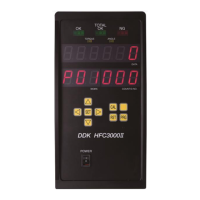
| Model | HFC3000II |
| Category | Power Tool |
| Language | English |