Chapter 9 External Interface
PAGE 9-11
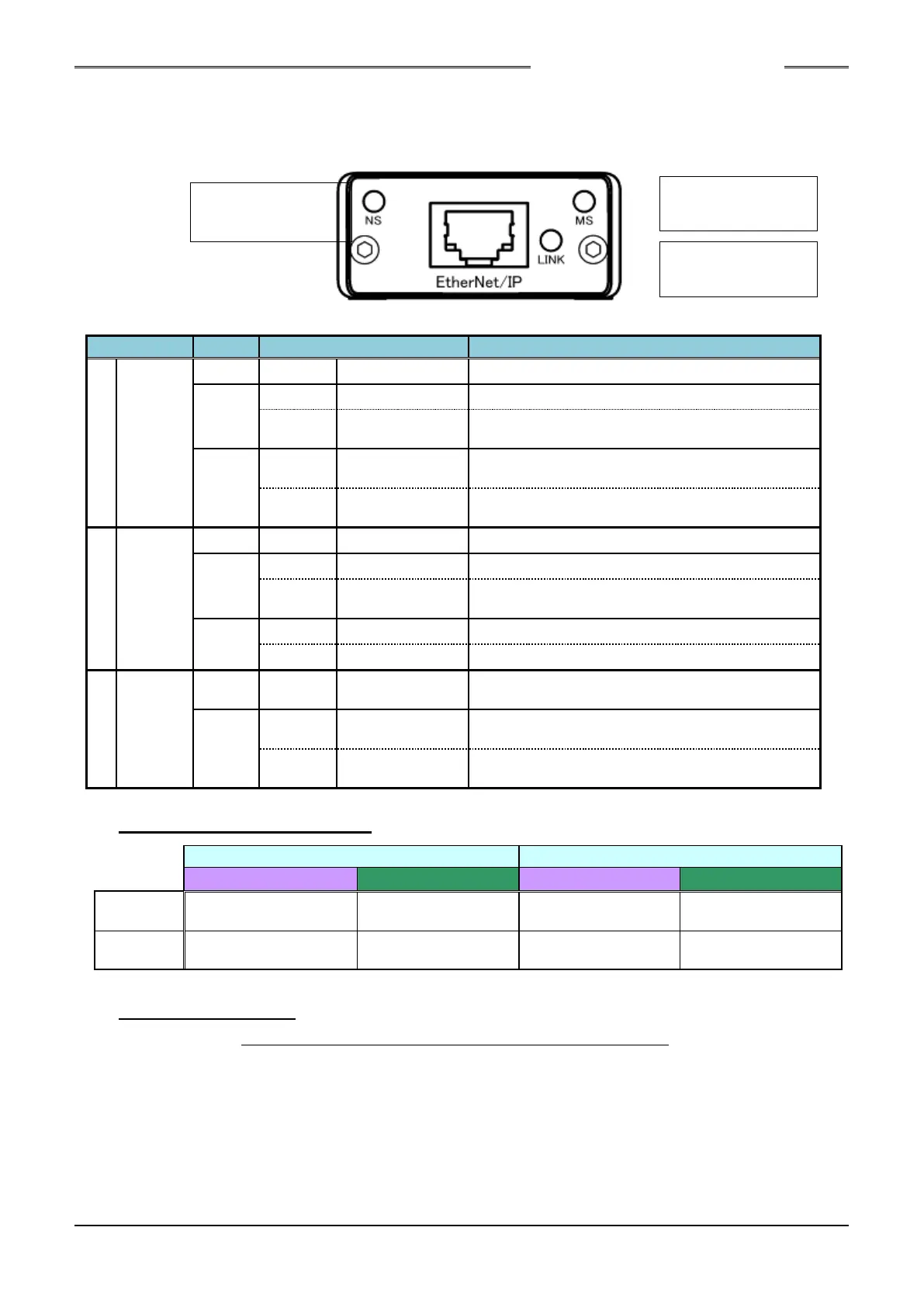
●List of LED Indications
The module LEDs indicate the states of the nodes of the HFC3000 EtherNet/IP System and the network
state.
9-2-3. I/O Signal Specifications
9-2-4. Fieldbus Setup
Please refer to S0140165 HFC3000 Omron PLC EtherNet/IP Connection Guide.
Offline or power is not supplied.
Communication
not established
Although online, connection is not established.
A critical error has occurred./ Redundant IP
address.
A connection timeout has occurred once or more.
Communication
not established
Due to incomplete configuration or connection
failure, the device must be re-recognized.
A critical error has occurred.
A recoverable error has occurred.
Ethernet link is not established and communication
is not performed.
Ethernet link is established but communication is
not performed.
Ethernet link is established and communication is in
progress.
S0140185-H
 Loading...