Chapter 4 Installation
PAGE 4-8
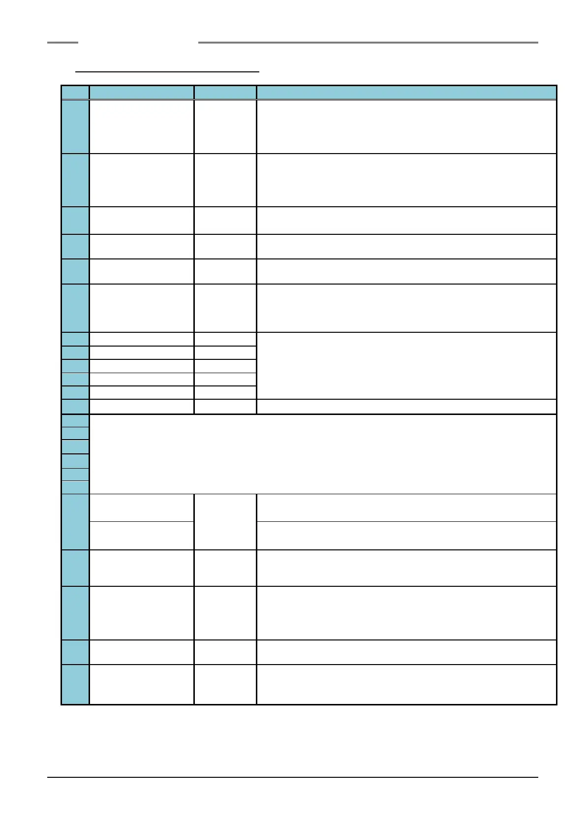
4-5-1. Controller Unit I/O Signals
Description of Function/Usage
The fastening operation is stopped by setting this signal to
“OFF”
Also, it is possible to change the setting of A contact / B contact.
System Parameter:SYS.033[xx1xxx] 0:A contact /1:B contact
Execute the following operation by setting this signal to “ON”.
・Stop tightening process.
・Set the PLC I / O fastening result signal of the controller to OFF.
・Delete the entered ID data.
While this is “ON,” the tool reversely rotates and in accordance
with the selected Work No.
The fastening operation in accordance with the selected work
No. is started by setting this signal to “ON.”
The Unit is put in the BYPASS (PROGRAM) mode while “ON” is
input.
When the START signal is set to “ON” while inputting “ON” into
this pin, the self-diagnosis of the torque transducer is skipped
before the start of the fastening operation
(The start of tool rotation can be shortened by approx. 60msec).
The WORK SELECT BIT 0 ~ 5 select signals enable selection
among parameter Nos. 1 ~ 64 by a combination of the 6 pin
Nos.
WORK SELECT BIT 5 is assigned to TB 3-9.
Bank changing input (Object :TB2-1~6 &TB3-7,8)
The name of the signal to be output changes according to the output status of TB 1-12 "BANK
SELECT".
(Reference 4-5-2.Input Signal: BANK SELECT)
Not connected internally
(relay contact-1、Controller software version V 1.006 or earlier)
Turns ON when manually starting the reversed operation.
(relay contact-1、Controller software version V1.007 or later)
Output ON / OFF of buzzer output linked externally.
(relay contact-2)
* Does not output sound when controller switch is selected
BATCH OK
[TOTAL OK]
(RY3-1)
Output when the fastening results are OK for the cycle count
times of fastening (relay contact-3)
Selection between pulse and level outputs is possible.
System Parameter:SYS.033[xxxxx1] 0: Continuous /1: pulse
Relay contact-1, 2, 3 common
QL OK (RY4-1)
[OK] (RY4-2)
OK output for QL signal (dry contact) (Relay contact-4)
Selection between pulse and level outputs is possible.
System Parameter:SYS.033[xxxxx1] 0: Continuous /1: pulse
* The pulse output length of BATCH OK and QL OK signals can be selected from the system
parameters.
System parameters: SYS.033 [xxx0xx] ... 300 msec
System parameters: SYS.033 [xxx1xx] ... 800 msec
(Continued on next page)
S0140185-H
 Loading...