e. Internal USB key, if installed
f. Processors and heat sink
CAUTION: To prevent damage to the processor pins when replacing a faulty system board, ensure that
you cover the processor socket with the processor protective cap.
g. Memory modules
Steps
1. Disconnect all cables from the system board.
CAUTION: Take care not to damage the system identification button while removing the system board from
the system.
CAUTION: Do not lift the system board by holding a memory module, processor, or other components.
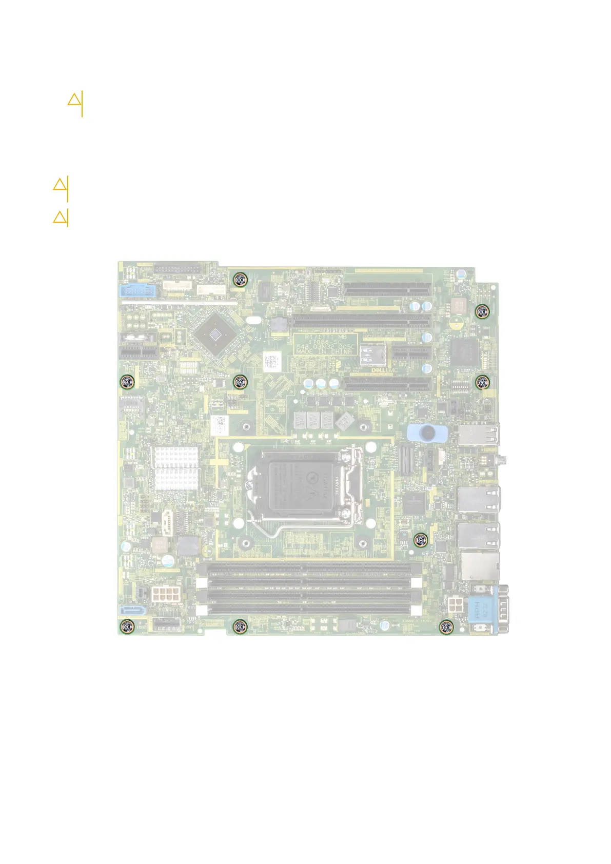
2. Using a Phillips #2 screwdriver, remove the screws that secure the system board to the system.
Figure 80. Removing the screws from the system board
3. Holding the post, incline the system board at an angle, and lift the system board out of the system.
Figure 81. Removing the system board
80
Installing and removing system components