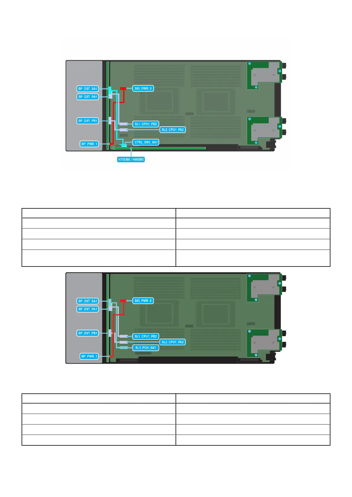
Figure 59. SAS/SATA/NVMe cabling diagram of configuration 8- 4 x 2.5-inch universal backplane with H755 MX or
H965i MX
Table 55. Connector descriptions for NVMe with H755 MX or H965i MX
From To
BP_PWR_1 (backplane power connector) SIG_PWR_0 (system board power connector)
BP_DST_PA1(backplane PCIe cable connector) SL1_CPU1_PB2 (signal connector on the system board)
BP_DST_PB1 (backplane PCIe cable connector) SL2_CPU1_PA2 (signal connector on the system board)
BP_DST_SA1 (backplane SAS/SATA connector) CTRL_SRC_SA1 (SAS/SATA connector of H755 MX or H965i
MX controller card, cable marking CTRL_PB1)
Figure 60. SAS/SATA/NVMe cabling diagram of configuration 10- 4 x 2.5-inch universal backplane
Table 56. Connector descriptions for SAS/SATA/NVMe
From To
BP_PWR_1 (backplane power connector) SIG_PWR_0 (system board power connector)
BP_DST_SA1 (backplane SATA connector) SL3_PCH_SA1 (signal connector on the system board)
BP_DST_PA1(backplane PCIe cable connector) SL1_CPU1_PB2 (signal connector on the system board)
BP_DST_PB1 (backplane PCIe cable connector) SL2_CPU1_PA2 (signal connector on the system board)
88 Installing and removing system components
 Loading...