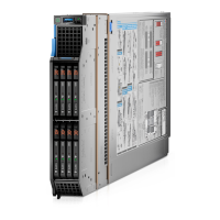
Figure 61. NVMe RAID cabling diagram of configuration 11- 4 x 2.5-inch universal backplane with H755 MX or H965i
MX
Table 57. Connector descriptions for NVMe with H755 MX or H965i MX
From To
BP_PWR_1 (backplane power connector) SIG_PWR_0 (system board power connector)
BP_DST_PA1(backplane PCIe cable connector) CTRL_SRC_PA1 (PCIe connector of H755 MX or H965i MX
controller card, cable marking CTRL_PA1)
BP_DST_PB1 (backplane PCIe cable connector) CTRL_SRC_PA1 (PCIe connector of H755 MX or H965i MX
controller card, cable marking CTRL_PA1)
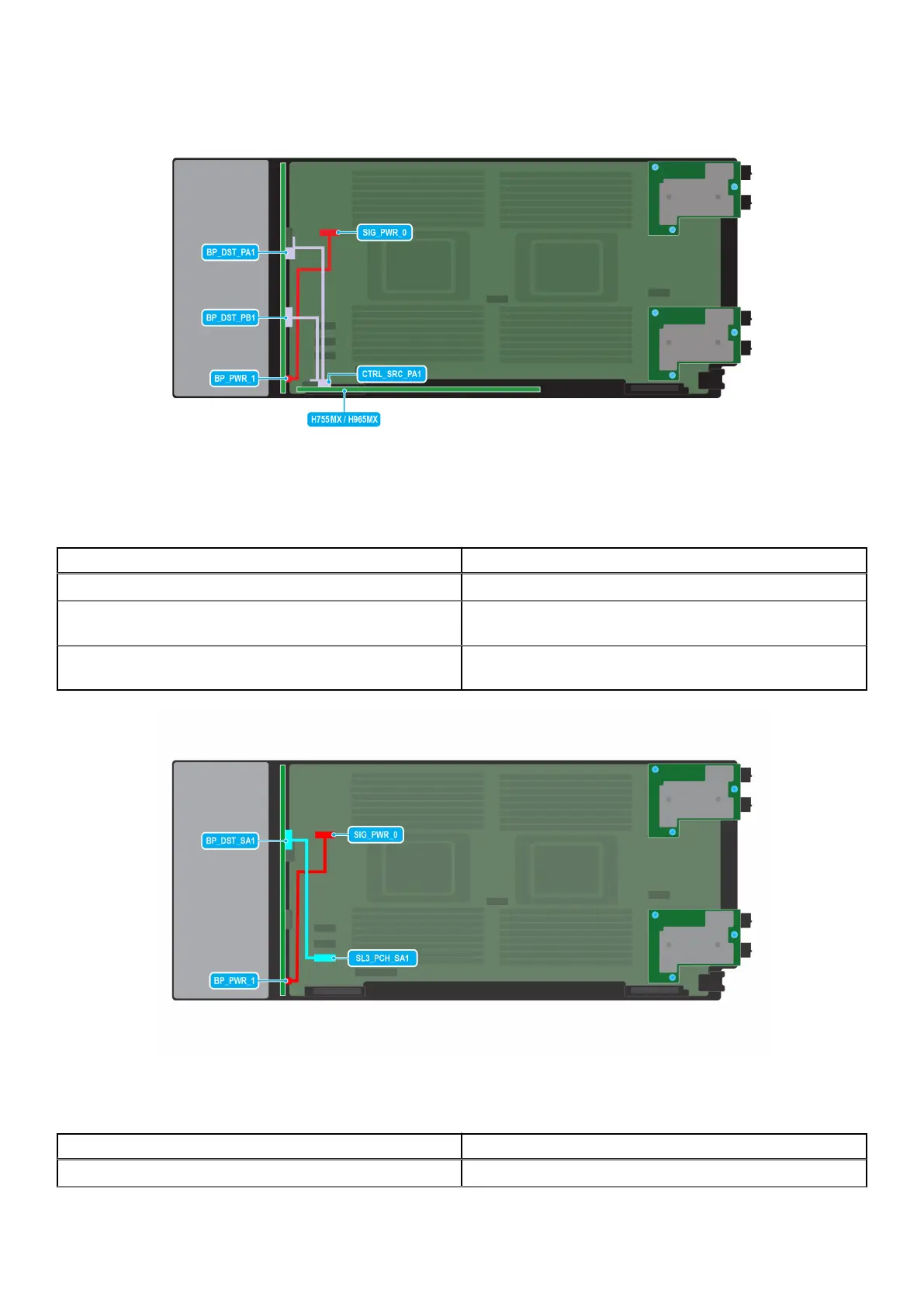
Figure 62. SATA cabling diagram of configuration 12 - 4 x 2.5-inch universal backplane
Table 58. Connector descriptions for SATA
From To
BP_PWR_1 (backplane power connector) SIG_PWR_0 (system board power connector)
Installing and removing system components 89