MATRIX Control Panel OP71 Assembly and Installation
PR-2009-0021-GB • Subject to modifications • R5-04/2016 19
5.3 Installation of the MATRIX control panel OP71
For connecting the MATRIX control panel OP71 only the following cross sections may
be used:
The following steps are required to connect the MATRIX control panel OP71:
– Connect mains electrical supply
– Connect MATRIX.Net
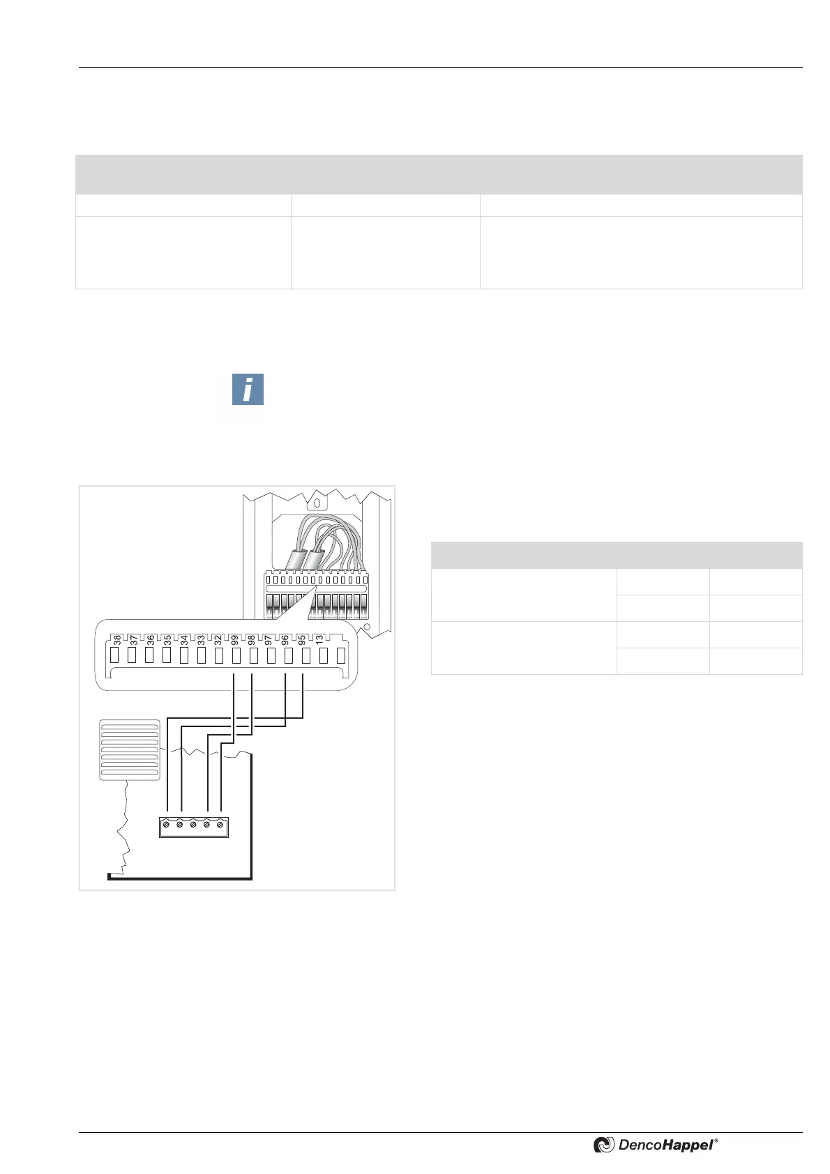
• Remove insulation from the wires and fasten each wire
according to the wiring diagram:
• Hook the front panel over the top of the mounting plate.
Apply light pressure to the bottom of the front panel until it
snaps into place.
Conductor type Number of conductors per
terminal
Cross-sections min to max
Rigid conductor cross-section 1 0.22 to 0.5 mm
2
Flexible conductor cross-section 1 0.22 to 0.5 mm
2
0.22 to 0.5 mm
2
tinned
0.22 mm with wire end sleeve (4-side crimping
tools, e.g. Knipex pliers/tongs 975304)
Note!
For setting up the MATRIX.Net use only data transfer cable certified according
to DIN 19245 T3 and EN 50170 as twisted-pair wire with braided shield.
We recommend:
- See also: „Cable recommendations MATRIX.Net“ on page 20
Terminal Signal
Supply voltage 95 GND
99 Vcc
MATRIX.Net 96 Low
98 High
 Loading...