Network MATRIX.Net MATRIX Control Panel OP71
28 PR-2009-0021-GB • Subject to modifications • R5-04/2016
7.2 Network structure MATRIX.Net
A network can consist of one or several (up to 16) groups. Global modules can also be
integrated into the network. The network structure / network topology of MATRIX.Net
is to be performed linearly – see “Topologies of network MATRIX.Net” on page 29.
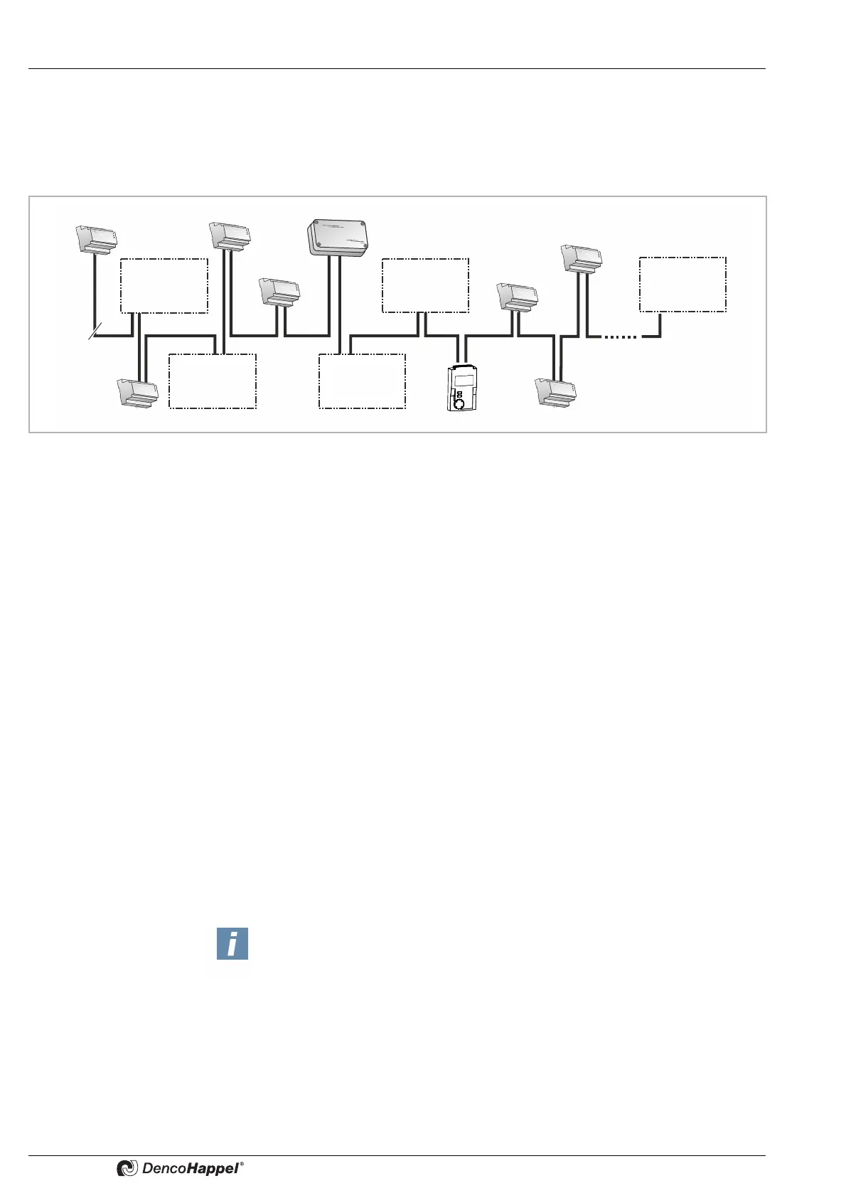
The maximum extent of the MATRIX.Net network is shown in Fig. 7-4:
Fig. 7-4: Example of maximum extent of the network
At its maximum extent, the network can consist of:
– a maximum of 16 unit groups – see “Topologies of network MATRIX.Net” on
page 29.
– two digital input modules (MATRIX.DI)
– two analog input modules (MATRIX.AI)
– two digital output modules (MATRIX.DO)
– one extract-air manager (MATRIX.EM)
– up to 16 LON
®
modules (MATRIX.LON)
– a maximum of 1 module MATRIX.LON can be assigned to each group
– to an intra-group control panel (MATRIX control panel OP71) *
*If a building management module (LON-Modul) gets registered in a group which is
assigned to a cluster with a MATRIX control panel for all groups OP71, an address
conflict will occur. Therefore the LON module and the MATRIX control panel OP71
must service different groups.
The arrangement of the unit groups and global modules in the network is ar-
bitrary. The following factors are critical for the assignment of units, control
panels and global modules to a group
– the setting of the group address switch (refer to the chapter “Commissioning and
Testing” in the relevant operation manual)
– or the assignment of a module input and output to a unit group via the MATRIX.PC
service tool (refer to Online Help for the Matrix.PC service software)
and not the physical assignment.
MATRIX.DI
MATRIX.EM
MATRIX.Net
MATRIX.DO
MATRIX.DO
MATRIX.AI
Group 2
Group 3
Group 1
Group 4
Group 16
Notice!
– If a MATRIX OP71 and a MATRIX.DI and/or MATRIX.AI are used in a
common network, the settings of the MATRIX OP71 assume higher priority.
Thus external settings are blocked and not implemented via the DI or AI
module. For example, deactivation of a unit using the input of the
MATRIX.DI ("unit off") with simultaneous setting of the fan mode via OP71
is not possible.
– Make sure that when using two .DI- or .AI modules, one group is always
acted upon from only one module ("A" or "B"). Any exceptions need to be
discussed with the factory.