LIST OF FIGURES
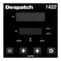
Figure 1. Operator Interface ......................................................................................................... 18
Figure 2. Typical Controller Output Sticker. ................................................................................. 20
Figure 3. Protocol Plus to Protocol 3 Connection Conversions. ................................................... 21
Figure 4. Protocol 3™ rear cover removed .................................................................................. 24
Figure 5. Protocol 3™ Ethernet module MAC address ................................................................ 24
Figure 6. Protocol 3™ Set IP Address ........................................................................................... 25
Figure 7. Protocol 3™ Assign Ethernet IP address ....................................................................... 25
Figure 8. Protocol 3™ Ethernet search for control ...................................................................... 26
Figure 9. Protocol 3™ Ethernet Modbus settings ........................................................................ 26
Figure 10. Protocol 3™ Ethernet communication check .............................................................. 27
Figure 11. Protocol 3™ Ethernet – controller online ................................................................... 28
Figure 12. Select a Mode Display. ................................................................................................. 31
Figure 13. Manual Mode Display Screen. ..................................................................................... 35
Figure 14. Timer Mode Display Screen. ........................................................................................ 37
Figure 15. Profile Mode. ............................................................................................................... 38
Figure 16. Main Menu. .................................................................................................................. 39
Figure 17. Profile Setup. ................................................................................................................ 40
Figure 18. Profile Setup Menu. ..................................................................................................... 42
Figure 19. Sample Profile. ............................................................................................................. 46
Figure 20. Sample Profile Values. ................................................................................................. 47
Figure 21. Recorder Control. ......................................................................................................... 53
Figure 22. Recorder Status. ........................................................................................................... 53
Figure 23. USB Menu. ................................................................................................................... 54
Figure 24. USB Port on Front Panel. ............................................................................................. 56
Figure 25. USB Files and Folders Requirements (as seen from Windows Explorer). ................... 56
Figure 26. Configuration Menu (see also Table 16 for more information). ................................. 59
Figure 27. How High, Low and Band process alarms are implemented. ...................................... 67
Figure 28. Service Information Screen. ......................................................................................... 73
Figure 29. Standard Digital Input Wiring. ..................................................................................... 74
Figure 30. Check Cabling. .............................................................................................................. 78
Figure 31. Older model serial converter schematic. ..................................................................... 79
Figure 32. Newer model serial converter schematic. ................................................................... 80
Figure 33. USB Converter Schematic. ........................................................................................... 81