148
ADJUSTMENTS - MAINTENANCE
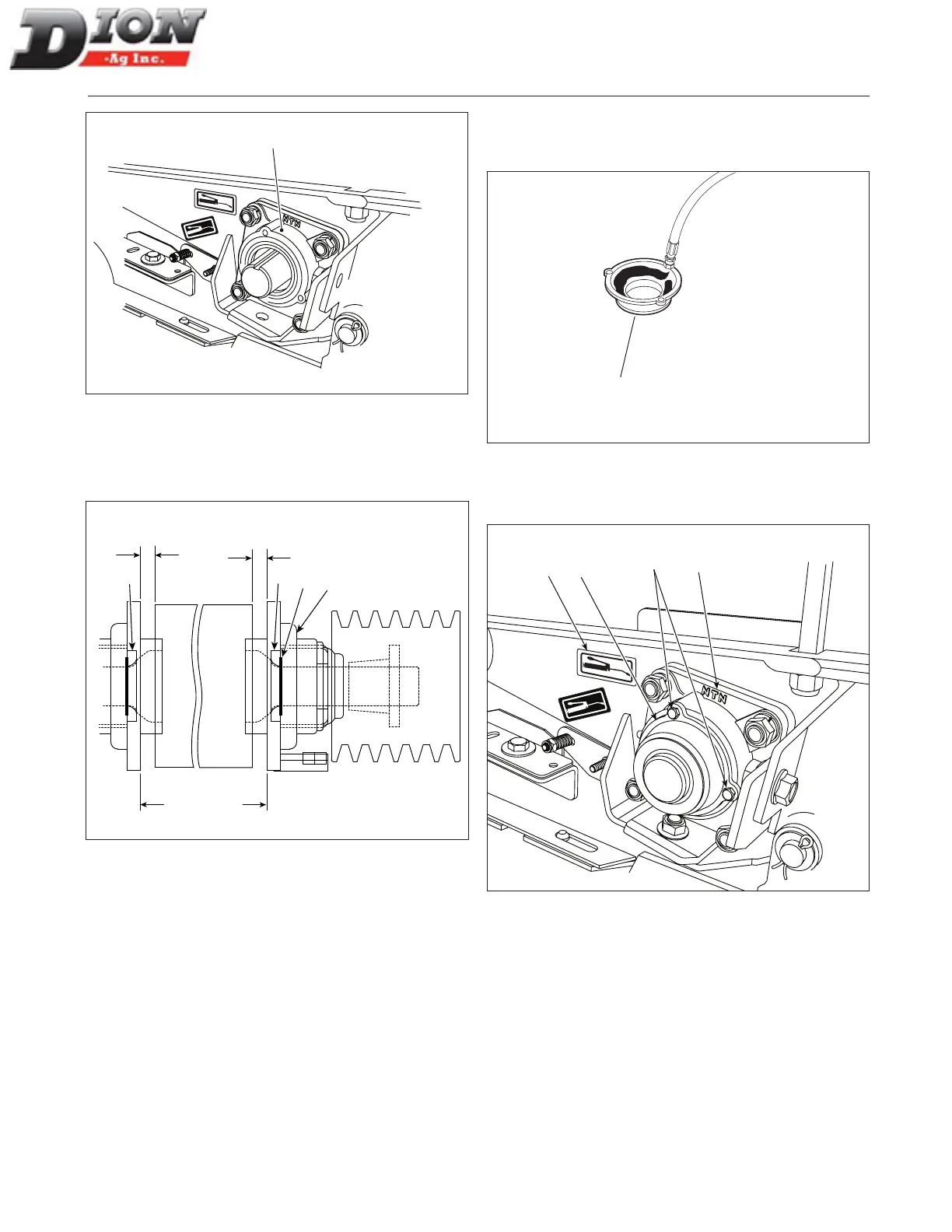
1
Figure 226
5. When replacing the upper roll, use 1/16” spacers
(item 10) in order to obtain the proper dimension
(Figure 227).
10
11
7
7
9/16” ± 1/16”
9/16” ± 1/16”
24 15/16”
24 13/16”
Figure 227
NOTE: When sliding the bearing on the shaft, make
sure the grease tting (item 10) is correctly ori-
ented so it can be easily connected.
NOTE: Apply “Loctite 262” to the set screws. Tighten
set screws to 45 in-lbs (5 N-m).
6. Fill the grease cap (item 2) carefully with grease
along with the cap seal ring contour. Leave a hole
according to the shaft diameter.
2
Figure 228
7. Bolt grease cap (item 2) with three bolts (item 3 - sup-
plied) and tighten securely.
1
3
2
10
Figure 229
8. Lubricate the grease tting (item 10) until grease
starts to exit from the hole under the support brack-
et (item 4).
NOTE: This will protect the bearing seal against contam-
ination from silage.
Manual No. F4117E987E V1.1