32
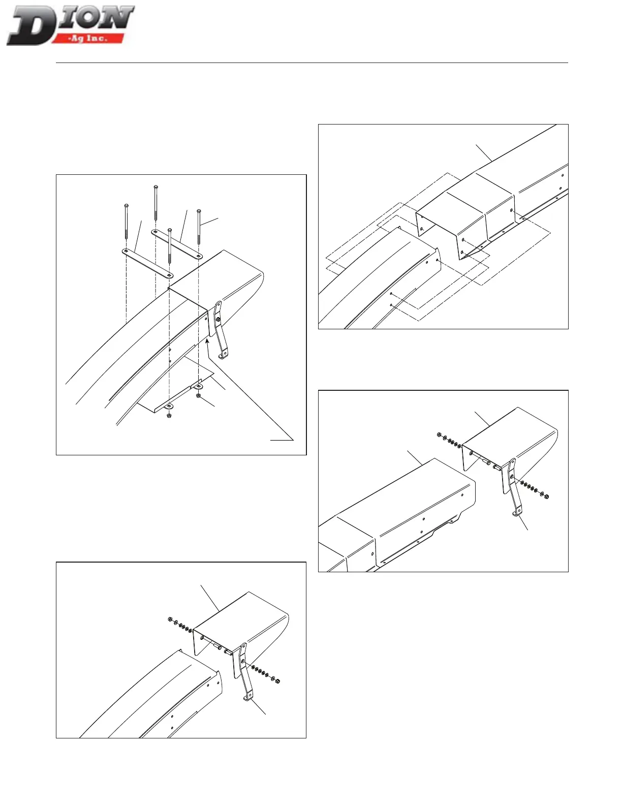
INSTALLING THE CLOSING PLATE ON THE SPOUT
1. Install the closing plate (item1) on the spout using
the two support brackets (item 2), four 5/16” X 6 1/2”
lg bolts (items 3) and four nuts (item 4).
2. Adjust the closing plate ush with the tip of the spout
as shown below.
3. Tighten all bolts and nuts properly.
3
4
1
2
2
Adjust plate flush
with tip of spout
Figure 16
INSTALLING THE 2’ (60CM) HORIZONTAL EXTEN-
SION - FIGURE 17, FIGURE 18 AND FIGURE 19
1. Remove the deector (item 1) and the spring plate
(item 2). Take note of the assembling order and
keep all bolts and nuts to reinstall these parts later
on in step 3.
1
2
Figure 17
2. Install the 2’ (60cm) extension (item 3), aligning it
with the three existing holes and using three 3/8” X
3/4” lg. ange bolts (heads on the inside) and three
3/8” ange nuts, on each side.
3
Figure 18
3. Reinstall the deector (item 1) and the spring plate
(item 2) on the extension (item 3). Make sure de-
ector is moving freely.
3
1
2
Figure 19
4. Replace the deector rope with a new, longer one,
4’ (120cm) long.
5. When a light is installed, also install a 2’ (60cm)
electric wire extension.
6. Bolt the closing plate using ve 5/16” X 1/2” lg ange
bolts and ve 5/16” ange nuts, on each side.
ASSEMBLING INSTRUCTIONS
Manual No. F4117E987E V1.1