156
ADJUSTMENTS - MAINTENANCE
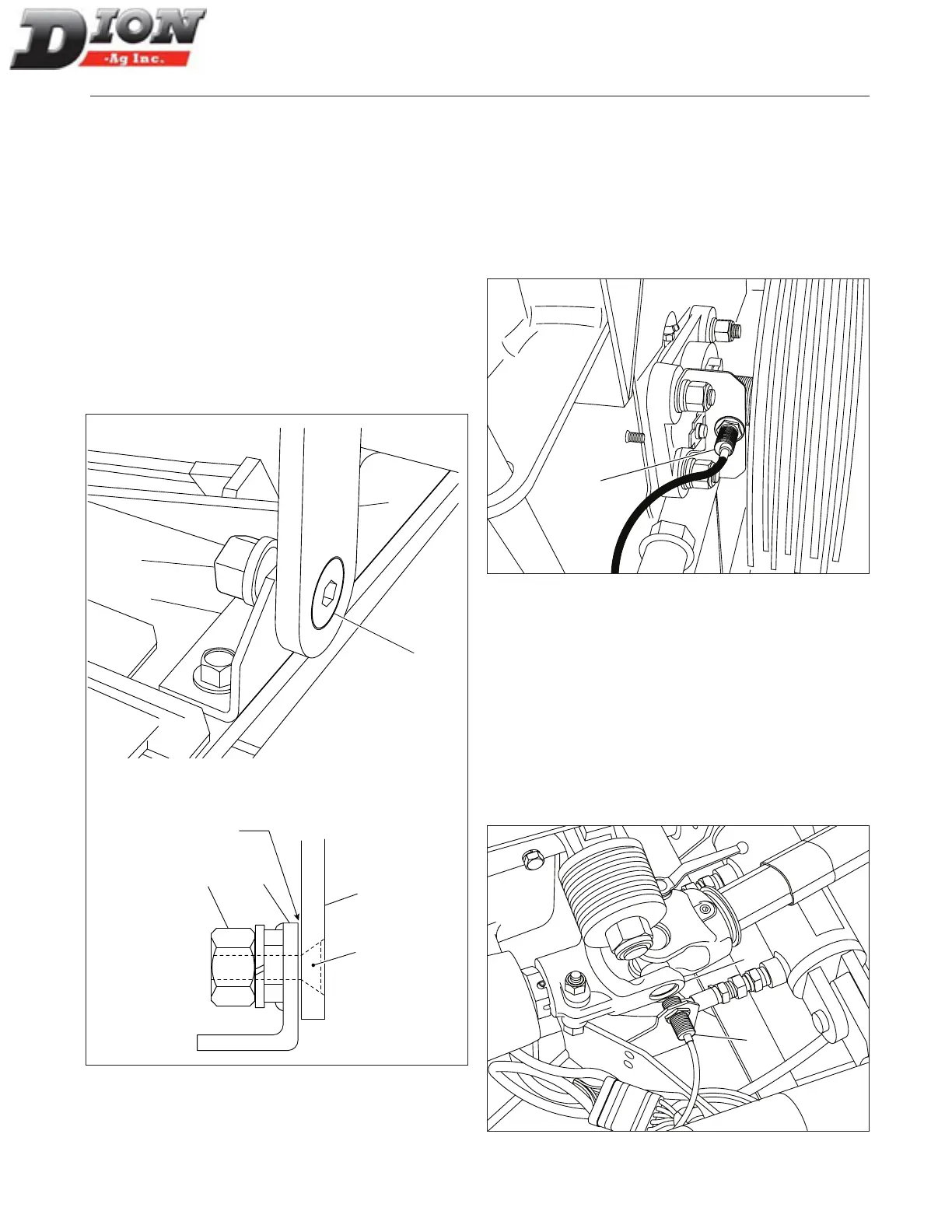
STONE CARRIAGE FRAME ADJUSTMENT
FIGURE 242
The proper frame adjustment must be checked once a
year to ensure a precise sharpening. to adjust:
1. Loosen the 5/8” nut (item 1).
2. Tighten the 5/8” X 2” lg at stove bolt (item 2).
3. Eliminate the backlash between the support bracket
(item 3) and the pivot (item 4) while making sure the
frame is free to pivot.
4. Tighten the 5/8” nut back (item 1) while keeping the
bolt (item 2) xed.
5. Carry out the same procedure for the other pivot.
6. Lubricate and make sure frame pivots freely.
1
2
4
3
1
2
3
4
Figure 242 Stone carriage frame adjustment
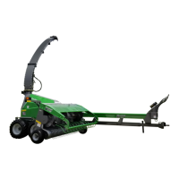
CUTTER HEAD SENSOR ADJUSTMENT
FIGURE 243
The sensor (item 1) on the nut of the cutter head shaft
must be adjusted so the sensor’s indicator light is
switched on when a corner of the nut is facing the sensor.
The indicator light must be switched off when the side of
the nut is facing the sensor. The adjustment is done by
loosening then tightening the nuts on the sensor.
1
Figure 243 Cutter head sensor
FEED ROLL SHAFT SENSOR ADJUSTMENT
FIGURE 244
The sensor (item 1) on the lower feed roll shaft must
be adjusted near the ange (item 2). Adjust the sensor
so it does not touch the ange. The indicator light on
the sensor must be switched on only when the ange is
facing the sensor. Use the nuts on the sensor to adjust,
then tighten properly. The indicator light must switch on
when the sensor is facing the eight corners on the uni-
versal joint ange.
1
2
Figure 244 Feed roll shaft sensor
Eliminate
backlash here
Manual No. F4117E987E V1.1