37
ASSEMBLING INSTRUCTIONS
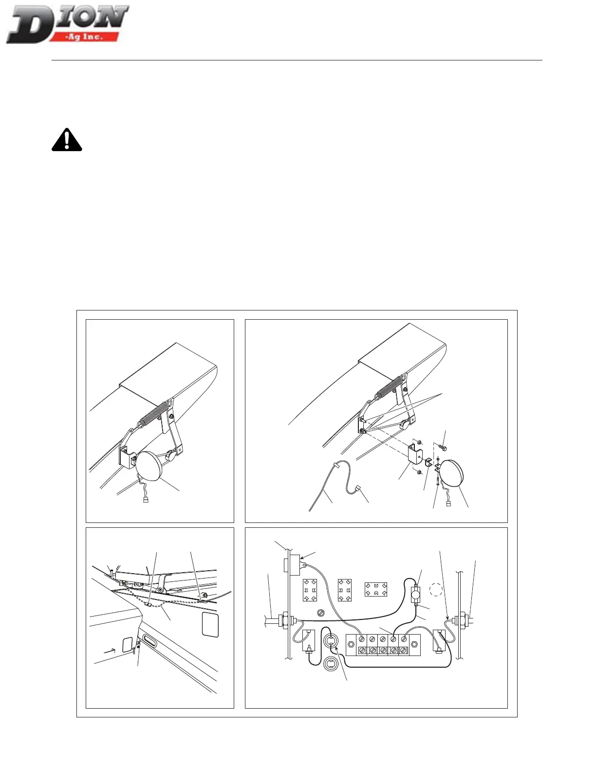
INSTALLING A LIGHT ON THE SPOUT
DEFLECTOR (F41 MODEL ONLY) - FIGURE 25
When the light (OPTION) on the spout deector has to
be installed, proceed as follows:
Quick disconnect the power cable (item 20) from
the control box before making the connections.
1. Open the control box (item 1) located in the tractor
cab. Install the toggle switch (item 2) and x it prop-
erly making sure, using an oheter, that current goes
through when the toggle switch is ”ON” as shown on
the control box decal.
2. Connect the white-yellow wire (item 4) on the ter-
minal (item 5) of the toggle switch.
3. Connect the supplied wire (item 6) to the other
switch terminal (item 7) and to the box terminal (item
8). Close the box cover and turn the toggle switch
”OFF”.
4. Bring the wire (item 9) down and run it through the
hole (item 10). Then, connect it to the plug (item
11) located underneath the guard and above the
sheave.
5. Bolt the light support bracket (item 12) using the two
existing bolts (item 13) of the spring support. Secure
the light assembly (item 14) to the support (item 12)
with the smaller support (item 18) and the supplied
bolt (item 15), one lock washer and one nut.
6. Bring the wire (item 9) along the side of the spout
and secure it with nylon tie-wraps.
7. Connect the plugs together (item 16). To adjust the
light direction, use bolts (items 15 and 17).
10
11
9
14
12
18
17
16
15
13
14
9
7
6
5
20
8
3
1
ALARM
MAIN TERMINAL (+)
MAIN POWER
EMERGENCY
STOP
white (+)
Figure 25 Spout deector light
Manual No. F4117E987E V1.1