89
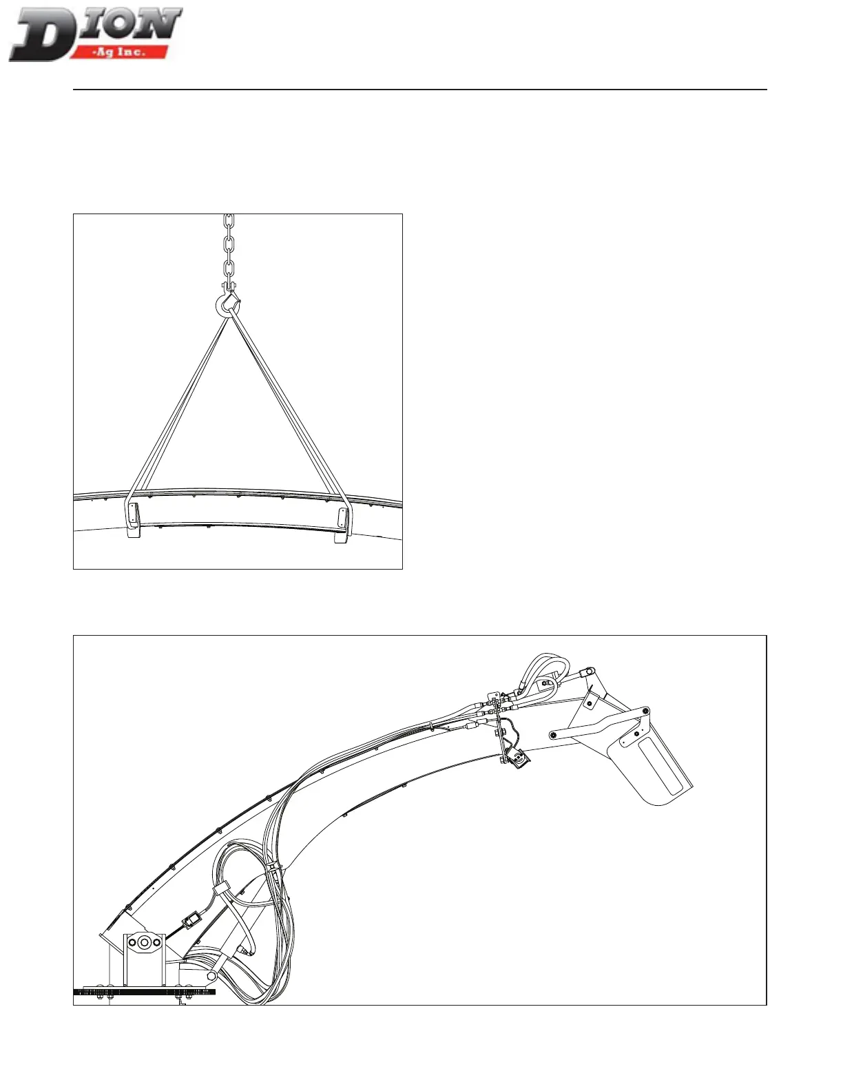
Step 4 (Figure 118)
1. Fasten the lifting straps on each side of the re-
inforcement brackets of the intermediate section to
lift and remove the middle section.
2. Protect the tips of all hydraulic hoses to prevent con-
tamination.
Figure 118 Removing the middle section
Step 5 (Figure 119)
Install the deector module on the base of the spout and
reconnect all hoses and wires.
HYDRAULIC SPOUT CONVERSION
Figure 119
Manual No. F4117E987E V1.1