Checking
the Generator for Proper
Operation
The proper operation
of
the
generator
should be checked
on
a spe-
cial benc
h:
in the motor dutv;
during
idling; -
under load.
In a
ll
checks, where application
of
vo
ltage is required, strictly
observe the polarity of
co
nnectio
n,
i.
e.
connect o
nl
y a
plu~
wire to
terminal "H".
Checking·
the
Generator
in the Motor
Duty
Th
e generator should
be
checked for mechanical
and
electrical
faults in the following order:
tLt;-n
the armature by hand
to
ch
ec
k it
fo
r free rotation;
remove the protective band, secure
the
generator
in
a holding
device on the bench and make connections as shown in
the
diagram
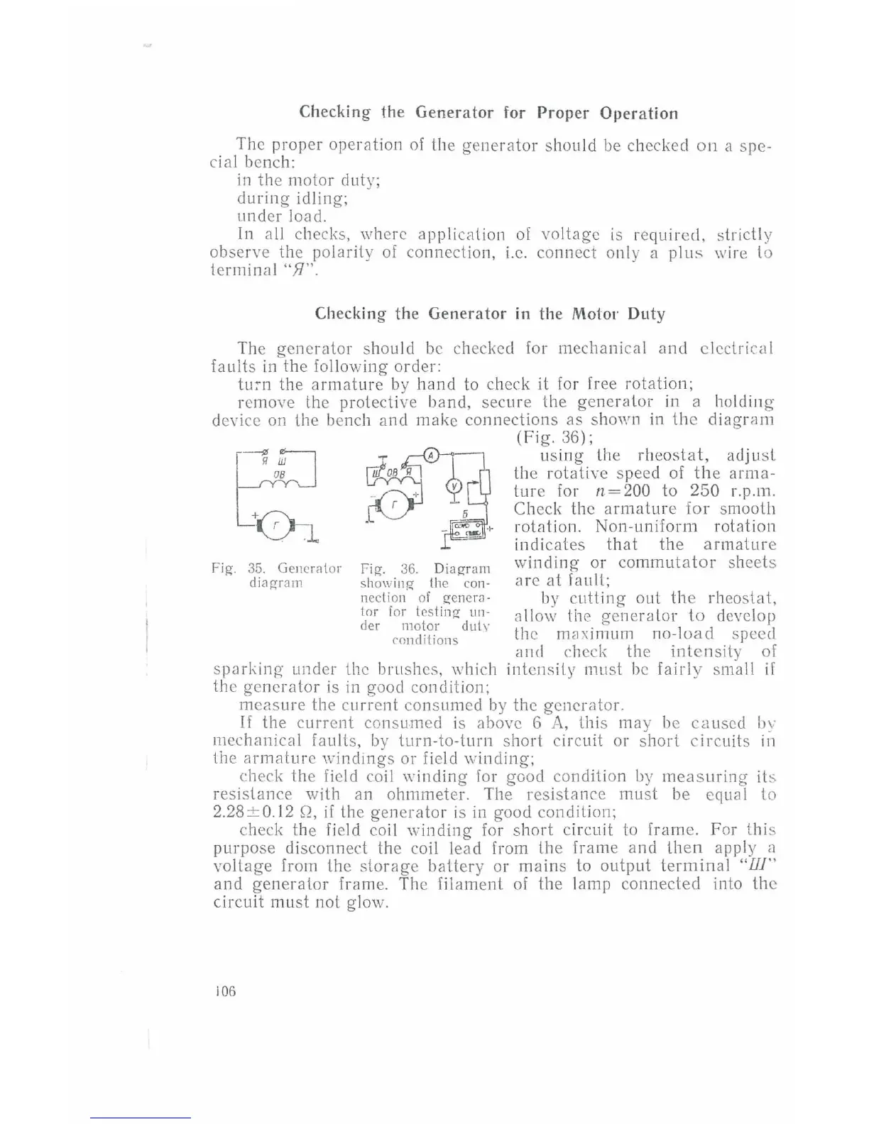
Fig. 35. Gen
era
lor
diagram
Fig. 36.
Diagr
am
sh
owing
lhe
con-
nection of
genern
·
tor
for
testing
un-
der
motor
duly
conditions
spnrking
under the brushes, which
the
generator
is
in good condition;
(Fig. 36);
usi
ng
the
rheostat,
adjust
th
e rotative speed
of
the
arma-
ture ior
n=200
to 250 r.p.m.
Check the
armature
for smooth
rotation. Non-uniform rotation
indicates
that
the
armature
winding
or
commutator
sheets
arc
at
fault;
by
cutting
out
th
e rheo
stat,
a
ll
ow
lhe generator
to
develop
the
mw-;imum no-lo
ad
speed
atiCl
check the
intensity
of
intensity mu
st
be
fairly
small
if
measure the
cu
rrent consumed
by
the generator.
If
the
current
consumed is above 6
A,
this may be
caused
bv
mechanical faults,
by
turn-to-turn short circuit or
short
circu
it
s
ii1
the arm
ature
windings or field winding;
check the field coil
\\·inding
for
good condition
by
measuring
its
resistance with an ohmmeter.
Th
e resistance must be equal to
2.28 ± 0.12
Q,
if
the
generator
is in good condition;
check the field coil
winding
for
short
circuit
to
frame. For this
purpose
di
sconnect the
co
il lead from the frame and
then
apply a
voltage from the stor
age
battery or mains to output
termin
al
"Ill"
and
generator
frame.
Th
e filament
of
the lamp connected into the
circuit must not glow.
106