•
•
Install lhe fourth
gear
on the knife-edges
of
an
appliance
DY-1697 and, using a mandrel 0-1696, press the shaft out
of
front
beari
ng
No
.
304.
Remove the front washer, fourth gear, gearshift sleeve and,
if
pos-
sibl
e,
the fourth
gear
bushing from the shaft.
I nsta
II
the second
gear
on the
knife-edges and, using a mandrel
p
0-1696, press the shaft
out
of
the
front sp lined sleeve, remove the
gears
and
gears
hift sleeve, then
ex-
tract lwo keys from the shaft slots,
lrim off the
burrs
on the edges
of
the
key slots and remove two bushings
of
the second a
nd
third gears,
if
these
ca n
be
removed manually.
If
not, the
bushings are pressed off the shaft
to-
gether with the
rear
splined sleeve.
In
sta
ll
the .first
gear
on the knife-
edges and press the shaft out
of
the
rea r splin ed sleeve.
Remove lhe first
gear
from the
shaft, then
ex
tr
act two keys from the
shaft slols, deburr lhe edges
of
the
key
slots and take out the first
gear
bushing.
Assemble the shaft
in
reverse or-
der. When assembling, lubricate all
the friction surfaces with
eng
in
e
oi
l.
On
comp leting the assembl
y,
ma-
ke
sure
that
all the
gears
are
free to
rotate around the shaft bushings.
After the l
ast
(bronze) bushing
has been pressed on the shaft, check
lo see
thal
it does not overh
ang
fr
om
the cylindrical surface
of
the
22
dia. shaft.
If
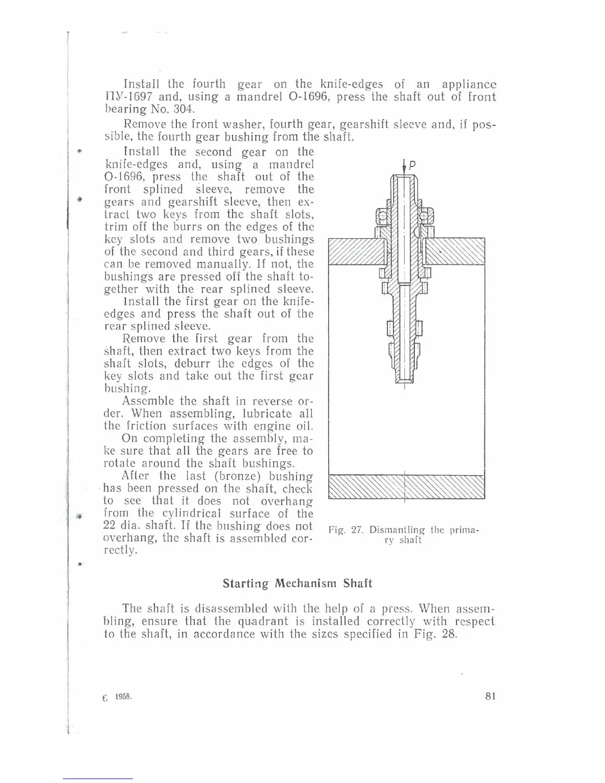
the bushing does not F'
2
-
o·
11·
!I ·
·
1g.
t.
!Sman
mg
1c
pnma-
overhang, the shaft is assembled
co
r-
ry
shaft
redly.
Starting Mechanism Shaft
The shaft is disassembled
·with
the help
of
a press. When
asse
m-
bling,
en
sure
that
lhe qu.adrant
is
installed correctly
wi
th res pect.
lo the sh8
ft,
in
accordance with the sizes spec
ifi
ed
in
Fig.
28.
f,
1958.
8 1