D3.n, dia. 0.72 mm,
25
turns,
one layer, counterclockwise winding
(lop view). ·
~
.
Shunt
wind
in
g
of
reverse-current relay: wire,
grade
D3
Jl,
dia. 0.17 mrn, 1
420±10
turns,
counterclockwise w
inding
(top
vi
ew),
resistance 37
~~
~
~2.
The
ser
ies
wi
nd
ing
I
I
consists
of
the
voltage
regulator
winding
(
1.5
turns)
ilnd rever
se-current
relay
wi
nding
(14.25
turns
\Vound
in
two
lilyers). Counterclockwise \\·inding.
Wire.
grade
D3B-2, dia. 1
.8
1 mm.
~
The resistors are
connected
in
5e
ri
cs wi
th
the shu nt
winding
of
the
Yoilagc reguliltor,
but
in
para
ll
el
with each other.
Th
e wirc-\vound re-
si
s
tor::;
are
rated
for
1.2
± I Q
(Ry),
dia. 0.5 mm,
grade
05
CU-X
l5I-l60
GOST
2338-58,
350 mm long,
and
for 4.4 ± 0.2 Q (R
"),
dia.
0.4
mm,
grade
Xl5H60
GOST
8803-58,
497 mm long.
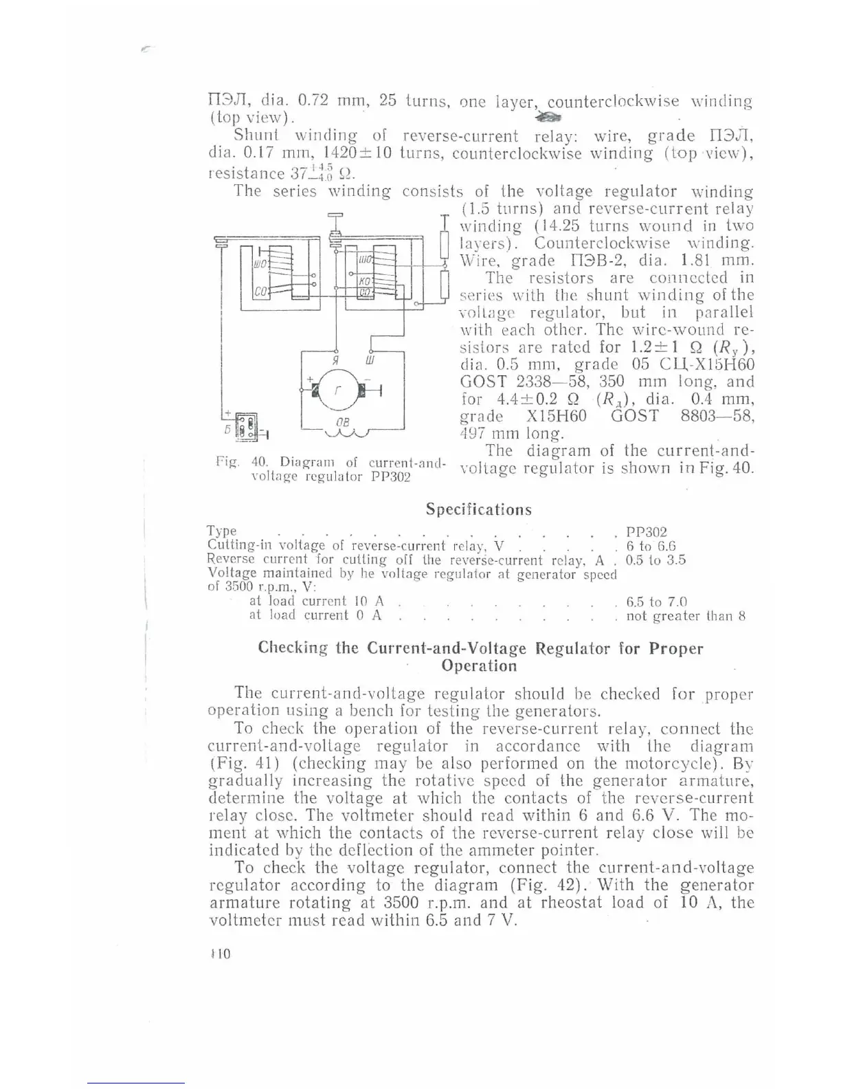
The
diagram
of
the
cur
rent- and-
Fig.
40.
Diagram
of
currenl-.1nd-
Yoltage regula tor
pp
302
voltage
regul<1tor is shown in Fig. 40.
Specif
ications
Type . . . . . . . . . .
Culling-in voltage
of
reverse-current
r·
elay, V . . . .
Reverse current
for
culling
off
lh
e reverse-current relay, A
Voltage maintained by
he
vo ltage
regul~tor
at
generator speed
of 3500 r.p.m.,
V:
al
load
cu
rrent
10
A
at
load current 0 A
PP302
6 to 6.6
0.5 to 3.5
6.5
to 7.0
not
greater
lhan 8
Checking
the
Current-and-Voltage
Regulator
for
Proper
Operation
Th
e
curre
nt
-a
nd-
vo
ltage
regulator
should be checked for proper
operation
using
a bench for
test
in
g lhe
genera
tors.
To check the
operation
of
the reverse-c
urr
ent relay, co
nn
ect the
current-and-vo
l
tage
regulator
in
accordance with
the
diagram
tfig.
4
1)
(checking
may
be also performed on the motor
cyc
le). By
gr
adua
ll
y
increasing
the
rotative
speed
of
the
generator
armature,
determine
the
voltage
at
which the
contacts
of
the r
everse-c
urr
ent
relay close. The voltmeter shou
ld
read
within
6
and
6.6
V.
The m
o-
ment
at which the
contacts
of
the reverse-current relay
close
will be
indicated by the deflection
of
the ammeter pointer.
To check the
voltage
regulator,
connect the
current-and-voltage
regulator
acco
rding
to the
di
agra
m (Fig. 42). With
the
generator
armature
rotating
at
3500 r.p.m.
and
at
rheostat load of 10
/\.,
the
vo
ltmeter
mu-st read within 6.5 and 7
V.
1
10