..
9
. ..
2.
REPAIRING
THE
1\'
,A
IN
DRIVE
UNITS
AND
COMPON[NT
PARTS
When
repairing
the mnin dri\'e units
and
component p
arls,
proper
attention should
be
given io ensu.re the correct
clc;mwces
and
in
le
r-
ferewes
hchrecn !he
mating
parts· in accordance with
the
data
li
st-
ed
in
Table 9.
In
order to
rl
elermi11e ,,·hclher son:e
of
the paris
are
good
for
further usage\ refer I
·J
T.:1ble
10
listing the maximum
permissib
le
values
of
-,,
·
ear
and
dcar
:
mces
in the basic
mating
members
.
Repairing
the
Propeller
Shaft
and
Universal
Jo:nt
Th
r propeller
shaft
and universal joint are subject io repairs in
c1se
any faults are cletect.ed during their
oreralion
(the propcl
tc·r
sh:dt
lJ'.
'nt, un
iy
ersa l joint
paris
or elastic cottpling worn) .
I
nspcct a
ll
the component
pa
rts
and
especially the m2tin5;
su
r-
facr".
cb
c
.-1\
the f
r;
l
lmring
pa r
ts
ior guod
co
nditio
n:
coupling
of
lhc fle'.ible universal joint;
splines
of
the propeller
shaft
;
needle b
eo
rings
of
lhc
un
iret·s8l joint cross;
ttni\'er"al joint fo
rk
s.
Hepl<~ce
lhc defeclive parts.
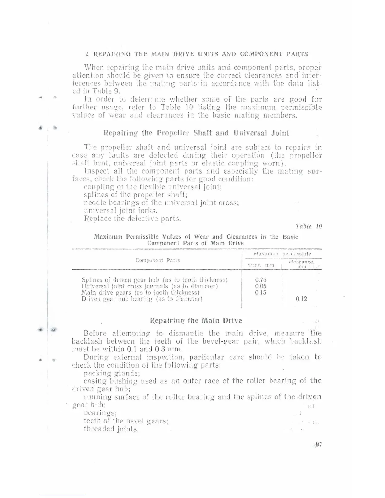
Tabl
e 10
Maximum
Permiss
ible
Values
of
Wear
and
Clear
ances
in
the
Basic
Comoonent
Parts
of
Main
Drive
---------,
S
plines
of dri1·en
gear
liub
(~s
to
tooth
thicknes
s)
Uni1·ers~l
joint
c;
oss
jownals
(
as
!o
diamc!
er)
Mai n
drive
gea
rs
(as
to loolil
thickness)
Driven ge2 r huh heJ
ring
(n 3
!o
diam
eter)
Rep
air
ing
th
e
Main
Drive
0.75
0.05
0.15
0.12
Before attempting- to
di
smanUc lhe ma
in
driw
,
measure
th
·e
backlash between the ieeth of lhe be\'Cl -gear p8ir, which backl
as
h
must
be
within
0.1
<Jn
d 0.3
rnm
.
Durin?;
e:-.:lc
;·n
nl inspection,
par
tic
ular
care sho•t!d
h•
taken
to
check the cond
iti
on
oi the
fo
llowing
p<~rts:
pa
ck
ing glands;
casing
bushing used
8S
an outer race
of
the roller bea
ri
ng
of
the
driven
gear
hub;
running
surface of ihc roller bea ring
and
the sp
li
nes
of
the dri
ven
gear
hub; ..
bearing
s;
teeth
of
the bevel gea rs; '·
threaded joints.