4.3 Network Connection
External Internet, TCP/IP equipment and Modbus equipment can be connected to the network router
inside the controller.
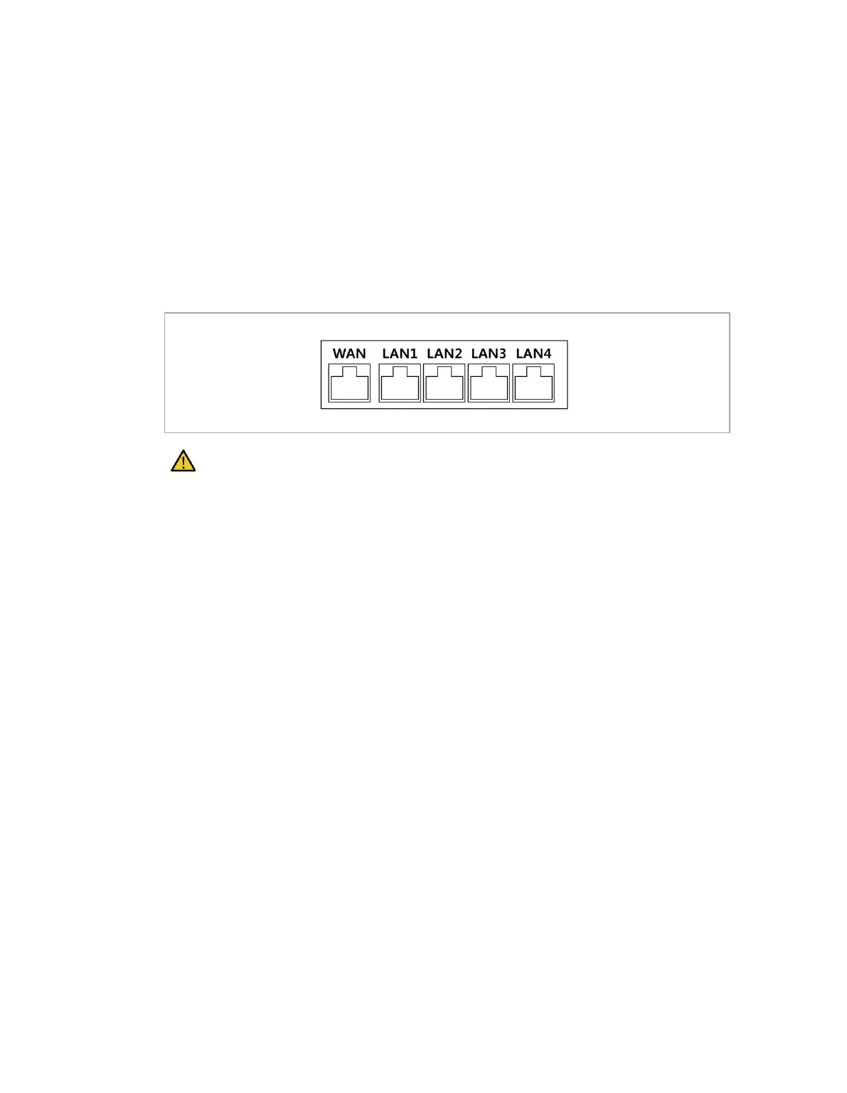
Connect cables to dedicated ports according to the network application.
• WAN: Connecting external Internet
• LAN: Connecting peripherals using TCP/IP or Modbus protocol
Connecting the cable to the network connection terminal will connect the network (refer to the figure
below).
Caution
The LAN4 port is used to connect internal controllers, so do not connect other equipment.
4.3.1 Connecting External Devices - Vision Sensor
The robot can be connected with a vision sensor (2D camera for object position measurement), and vision
sensor measurements can be transferred to the robot through a network to link with commands of the
robot.
Vision Sensor Setting
◼ Communication Connection Setting
Connect the LAN ports of the devices and apply TCP/IP communication to transfer vision sensor
measurements to the robot. (refer to LAN port connection “4.3 Network Connection”) Set the IP
address of the vision sensor to TCP/IP 192.168.137.xxx band to allow TCP/IP communication.
◼ Vision Work Setting
To perform object position measurement, it is necessary to have an image input and vision teaching of
the target object using the vision sensor. Refer to the dedicated vision work setting program provided
by the vision sensor manufacturer.
 Loading...