- Rotating Atomizer with External Charging
Version:: 07 • As of:: 01/2020
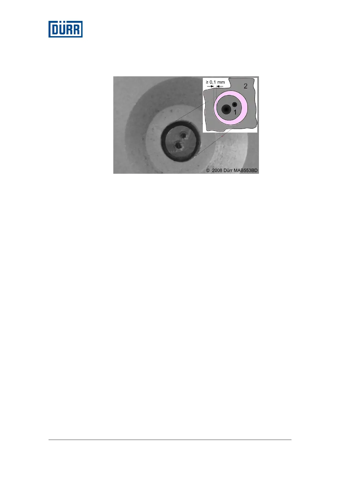
Fig. 71: Test sleeve, clearance for nozzle centering
1 Nozzle
2 Test sleeves
Should the tip of the nozzle not be in the correct position, it can be
corrected using the following steps.
• Disassembling the turbine.
• Dismantle the paint tube.
Paint tube and seat of the paint tube must be clean.
• Assemble the paint tube.
Pay attention to the correct position and the correct tightening
torque.
• Install the turbine.
Then the position of the nozzle must be checked again.
Pos: 63 /INP/ Bell2/08_07 L ichtleiter aus _ein @ 40\mod _141104122 9328_20. docx @ 502552 @ 2 3333 @ 1
9.3 Installation of the light conductor
In order to assemble the light conductor, the valve block must be
removed and dismantled from the turbine. Information about this is
available in the chapters "Remove Valve Block" and "Remove
Turbine."
9.3.1 Removing the light conductor
In order to remove the light conductor, you must first remove the
chuck.
• Loosen screws on the inside of the valve block.
The screws are secure against loss. The screws need to be only
loosened and not removed completely.
 Loading...