GBK51948 RHINO2
Installation Manual Issue 5
will be prevented until the throttle has been returned to neutral. Since an OONAPU test will be triggered in this
situation, even though the drive inhibit is programmed to be NOT latching, a latched OONAPU fault may be
generated if the throttle remains deflected after the inhibit is activated, and this OONAPU fault would then
require that the controller power is cycled.
If Flashes is set to Yes, then the drive inhibit status indication will be displayed regardless of the setting of the
Latches parameter for the corresponding input. If Flashes is set to Yes and Latches is set to no then the drive
inhibit indication will be displayed for as long as the corresponding input remains active while the throttle is
deflected (in the inhibited direction for the case of directional Stop function).
6.5.9.2
If a pin is in its active state, the corresponding function will be executed. The input pins can
be set to the following Active States:
Low — Input is active when pulled down, inactive when open or pulled up
High — Input is active when pulled up, inactive when open or pulled down
Open — Input is active when open, inactive when pulled up or pulled down
Low or High — Input is active when pulled down or pulled up, inactive when open
Low or Open — Input is active when pulled down or open, inactive when pulled up
High or Open — Input is active when pulled up or open, inactive when pulled down
Figure 60: Pulling inputs up/down
To pull up an input, connect it to B+. To pull down an input, connect it to B-.
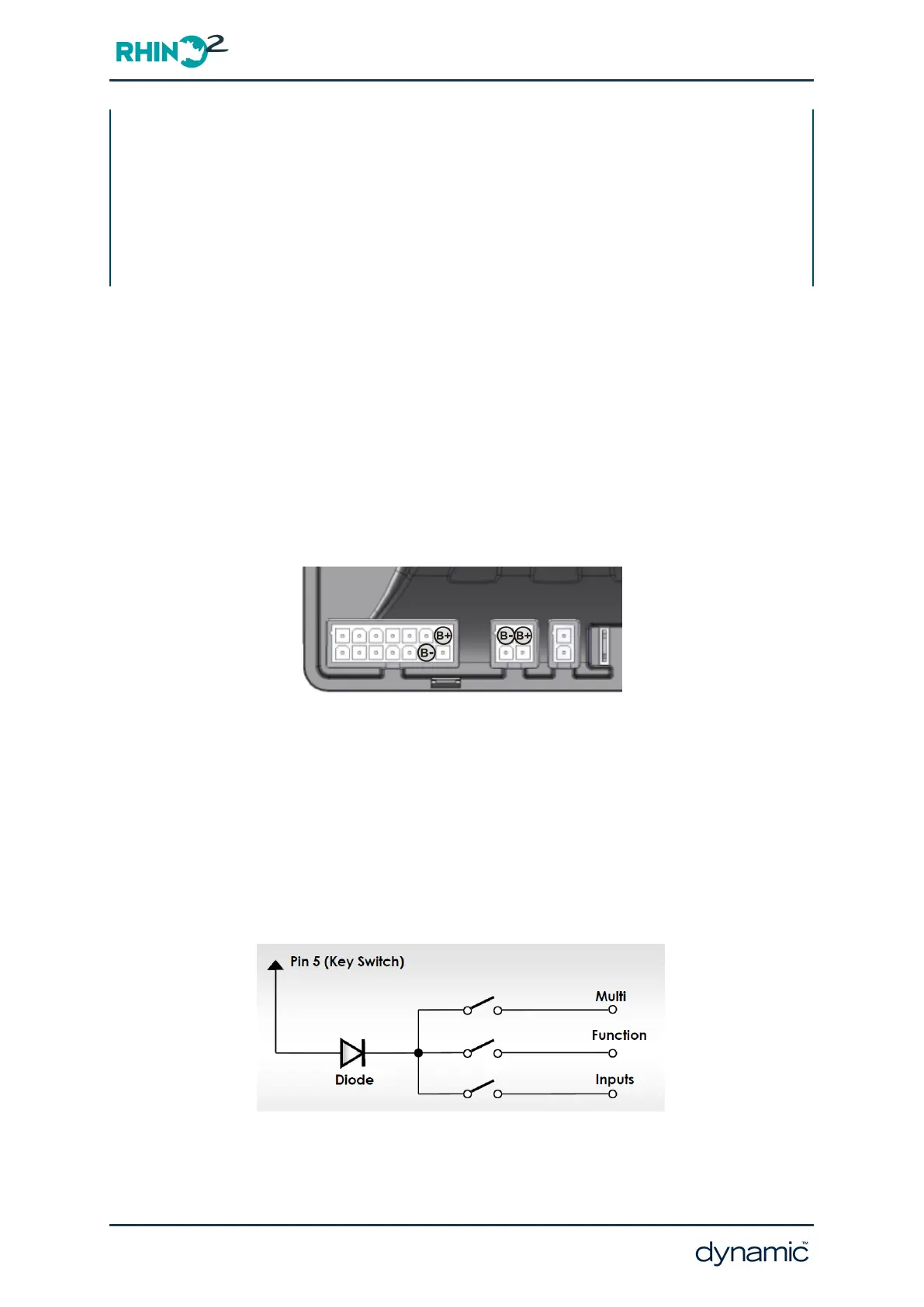
If a multi-function input switch is connected to Pin 5 (Key Switch), put a diode in series for
increased reliability. If multiple switches are connected to Pin 5 (Key Switch), it is not
necessary to add a diode for each of them. One diode for all multi-function input switches
combined is enough. Insert the diode as close to the switches as possible.
Figure 61: Put a diode in series if switches are connected to Pin 5 (Key Switch)
Page 116 - Programming