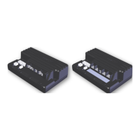
GBK51948 RHINO2
Installation Manual Issue 5
5.3 Connections and Wiring
5.3.1 General Wiring Recommendations
To maximise performance, minimise EMC emissions, maximise EMC and ESD immunity, and
to keep the cabling of the scooter safe and tidy, please observe the following guidelines.
l
Keep all cables as short as possible.
l
Avoid wire loops, especially loops of single wires instead of wire pairs.
l
Try to run wires in pairs or bunches. For example, run the battery positive and
negative wires together and the motor positive and negative wires together. Bind
wires together and fix them to the chassis.
l
Do not route the cables (including the motor cable) near the motor case, where
possible.
l
Do not leave electrical connections unnecessarily exposed. Insulate exposed
connections (for example with sleeving) to reduce the risk of short circuits, exposure
to water and connection stress.
l
Make sure that all vehicle sub-frames, particularly the transaxle, controller case and
tiller head assemblies, are electrically connected.
l
Make sure that the controller and speed setting potentiometers are electrically
connected to the vehicle frame.
l
Do not use the vehicle frame as the earth return. Any electrical low-resistance
connection to the frame is a safety risk and is not allowed by international safety
standards.
l
To minimise electromagnetic emissions by the motor brushes, it may be necessary to
fit capacitors between the brush holders and the motor case. Make sure that the
leads are kept as short as possible. A suitable capacitor is 4n7, 2kV Ceramic.
l
For best electrical performance, the wire size must be as large as possible.
Recommended minimum wire sizes are shown in the wiring sections.
l
For low-current signals, do not use wire sizes smaller than 0.5mm
2
/AWG20, because
smaller wires are physically not strong enough for this application.
l
Make sure that only supplied terminal screws are used.
l
The type of cable used must be appropriate for the mechanical and environmental
abuse it is likely to encounter.
l
Do not use damaged or abused cables. A damaged cable can potentially produce
localised heat, sparks or arcing and as such it can cause a fire.
l
Protect all cables against possible contact with flammable material.
l
All cables used should be resistant to fire to VW-1 (UL 1581) or similar.
l
The installation must prevent and/or discourage the user from accessing any cable.
l
While assembling the terminal cover, make sure that the wires are not trapped under
the cover.
l
While installing power and battery connectors of DS90 and DS120 variants, make
sure to insert until you feel them click into position.
l
Refer to sections 5.3.2 Wiring Diagram for DS90 and DS120 and 5.3.3 Wiring
Diagram for DS160 and DS180 for wiring diagrams for all RHINO2 variants.
Page 20 - Installation and testing

 Loading...