GBK51948 RHINO2
Installation Manual Issue 5
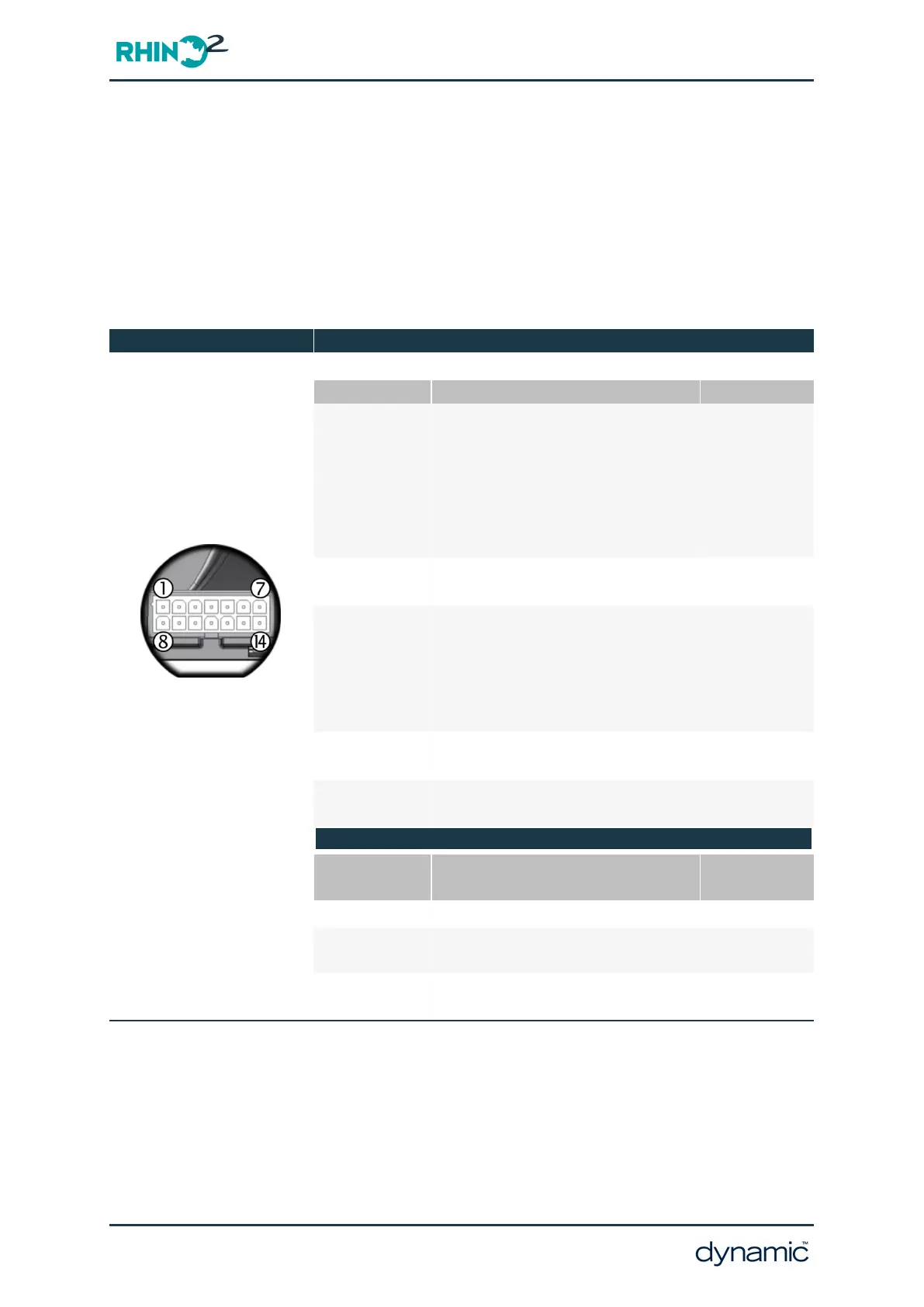
5.8 Tiller Connector
The tiller connector provides all the connections necessary to power and control all the
functions contained in the tiller head. This connector also supports the new Multifunction
pins that can be configured for alternative functionality depending on application
requirements.
Where the Multifunction pins are listed below, the bold text indicates the recommended
default functions.
Tiller Connections
Pin Function Wire Gauge
1 Throttle Wiper (TW)
0.5mm²
(20AWG)
2 Throttle Positive (T+)
3 Multifunction Output (Beeper)
4 Multifunction Input (Profile 2)
5 Key Switch (KS)
6 Multifunction Input (Slow)
7 Battery Positive (B+)
1.0mm²
(18AWG)
8 Throttle Negative (T-)
0.5mm²
(20AWG)
9 Speed Limit Pot (SLP)
10 Multifunction Output (Status Low)
11 Multifunction Output (none)
12 Multifunction Input (Reverse Drive)
13 Battery Negative (B-)
1.0mm²
(18AWG)
14
Multifunction Input (Charger Inhibit)
0.5mm²
(20AWG)
Mating Connector Part Numbers
Dynamic Part # Part Description
Supplier Part
#
GCN0887 Molex ‘Mini-Fit Jr’ 14-socket housing 39-01-2145
GCN0776
Molex ‘Mini-Fit Jr’ Receptacles
16AWG (0.8 – 1.3mm² wire)
39-00-0212
GCN0771
Molex ‘Mini-Fit Jr’ Receptacles
18-24AWG (0.2 – 0.8mm² wire)
39-00-0039
Page 34 - Installation and testing