See 6.1.1.3 Throttle calibration in the programming section for details.
Note
To calibrate the throttle with the Wizard PC-based programmer, use the HHP emulator mode:
Tools -> Plug-ins -> HHP Emulation
5.9.6 Speed Limit Pot Connections
A speed limit pot may be connected either in series with the throttle wiper, or in parallel by
using the dedicated input Pin 9 (Speed Limit Pot wiper), Pin 2 (Throttle Positive) and Pin 8
(Throttle Negative).
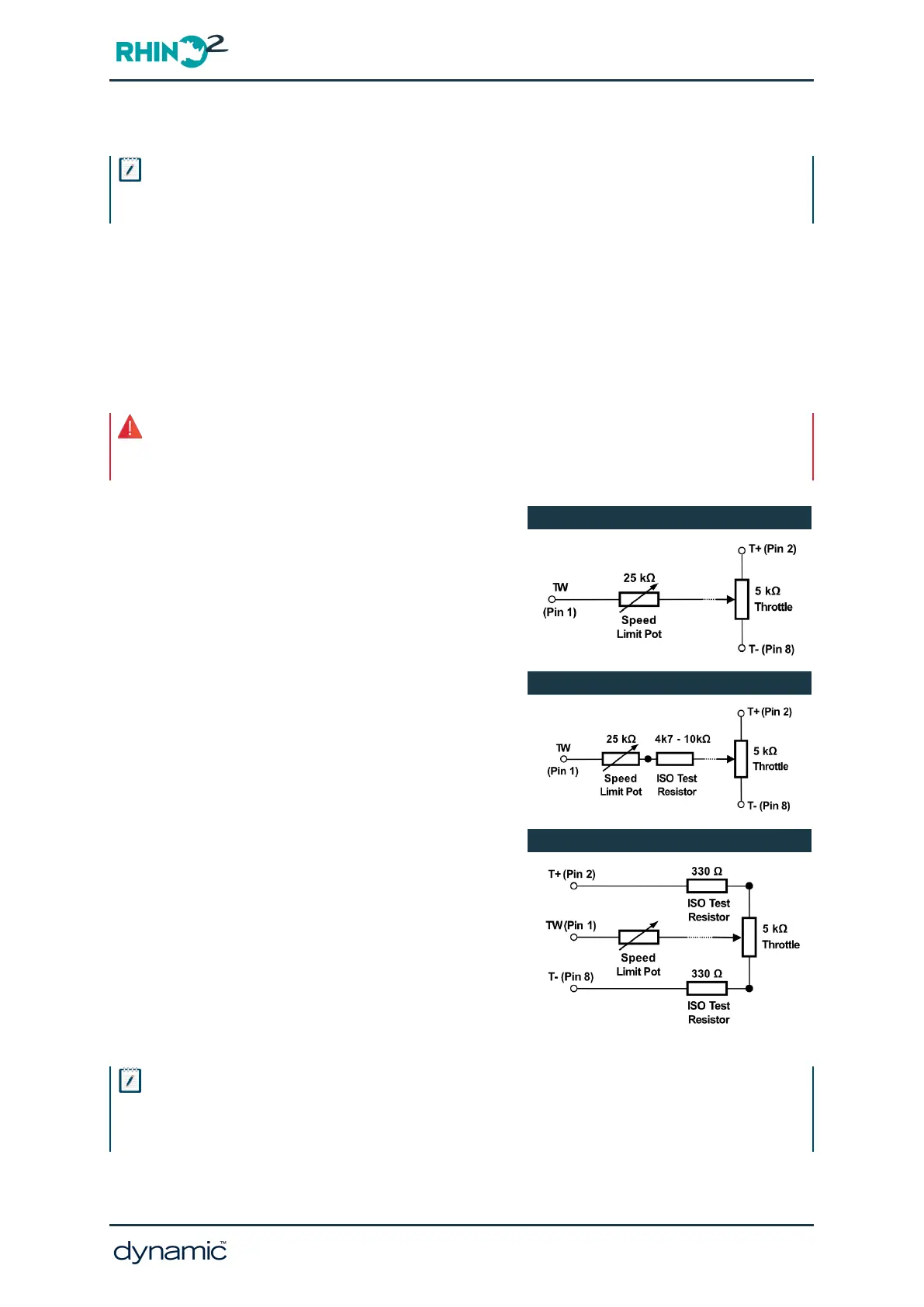
5.9.6.1 In series with the throttle wiper
Warning
If a series speed limit pot is used, the system will be unlikely to satisfy all of the requirements of ISO7176-
14:2022 Clause 7.2 “Controller command signal processing failure”.
If wiring in series, use a 25kΩ potentiometer and set
Speed Limit Pot to 'No', because the dedicated speed
pot input (pin 9) is not used.
To increase the chance of detecting short-circuit
faults in the throttle wiring, use an ISO test resistor
between the throttle wiper and the speed pot. The
ISO Test resistor must be placed as close to the
speed pot as possible, preferably directly soldered
with as short a lead as possible and mechanically
protected.
As an alternative to wiring a single ISO Test Resistor
in the Throttle Wiper, two ISO Test Resistors may be
added to the Throttle Positive and Throttle Negative
terminal of the throttle potentiometer. This will,
unfortunately, increase the susceptibility of the
throttle circuit to leakage. The 2 ISO resistors must
be placed as close to the throttle pot as possible,
preferably directly soldered with as short a lead as
possible and mechanically protected.
Speed Pot in Series
Speed Pot in Series with ISO Resistor
Speed Pot in Series with 2 ISO Resistors
Note
If ISO test resistors are used then it may be necessary to adjust:
1. the Throttle Calibration settings ( 5.9.5 Throttle Calibration)
2. the Throttle Configuration parameters ( 6.5.2 Throttle Configuration).
GBK51948 RHINO2
Installation Manual Issue 5
Installation and testing - Page 41