Alternatively, any of the Multifunction Input pins that support the Slow function may be
used. In this case, set Slows to to 0 and set Latches to 'Yes'. If Latches is set to 'Yes', a
power cycle is required to be able to drive again. If Latches is set to 'No', removing the
battery charger will allow driving immediately.
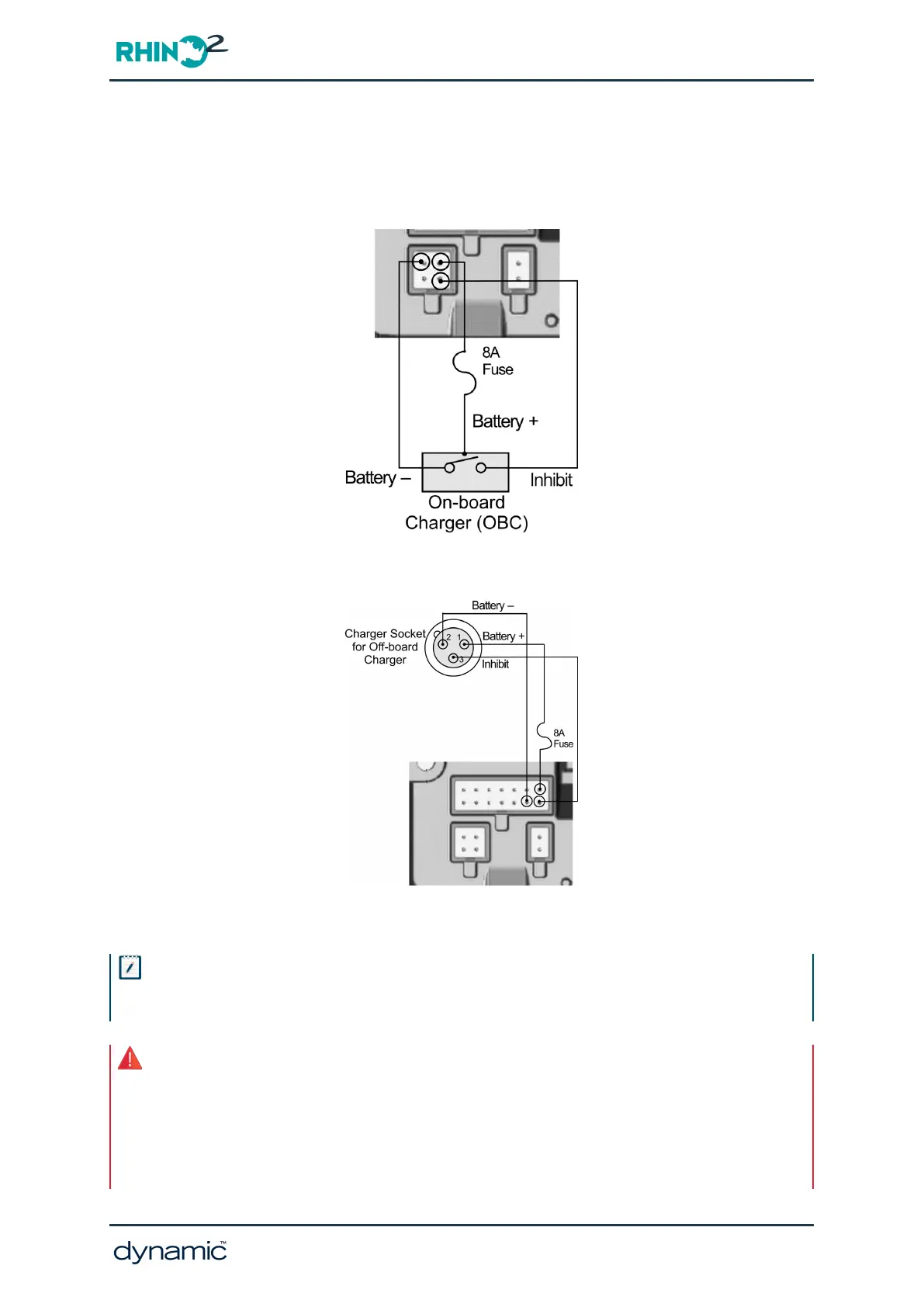
Figure 17: Example of On-board charger wiring (shown using Charger/Programmer connector)
Figure 18: Example of Charger Socket wiring for an Off-board charger (shown using the tiller connector)
Note
The inhibit pin is a Multifunction input and can be used for an alternative function if a charger is not plugged
into this pin.
Warning
1. A suitable fuse, with a maximum rating of 8A, must be installed in the Battery Positive wire to protect the
scooter’s wiring. Connect the fuse as close as practical to the controller connector to minimise the length of
unprotected wiring.
2. The Battery Positive (B+) wires (pin 2 of the 4-pin connector, and pin 7 of the 14-way connector) should be
coloured “RED” to conform to ISO 7176-14.
GBK51948 RHINO2
Installation Manual Issue 5
Installation and testing - Page 31