INSTALLATION
Dyno Installation
Version 5 Model 200i and 250i Motorcycle Dynamometer Installation Guide
2-5
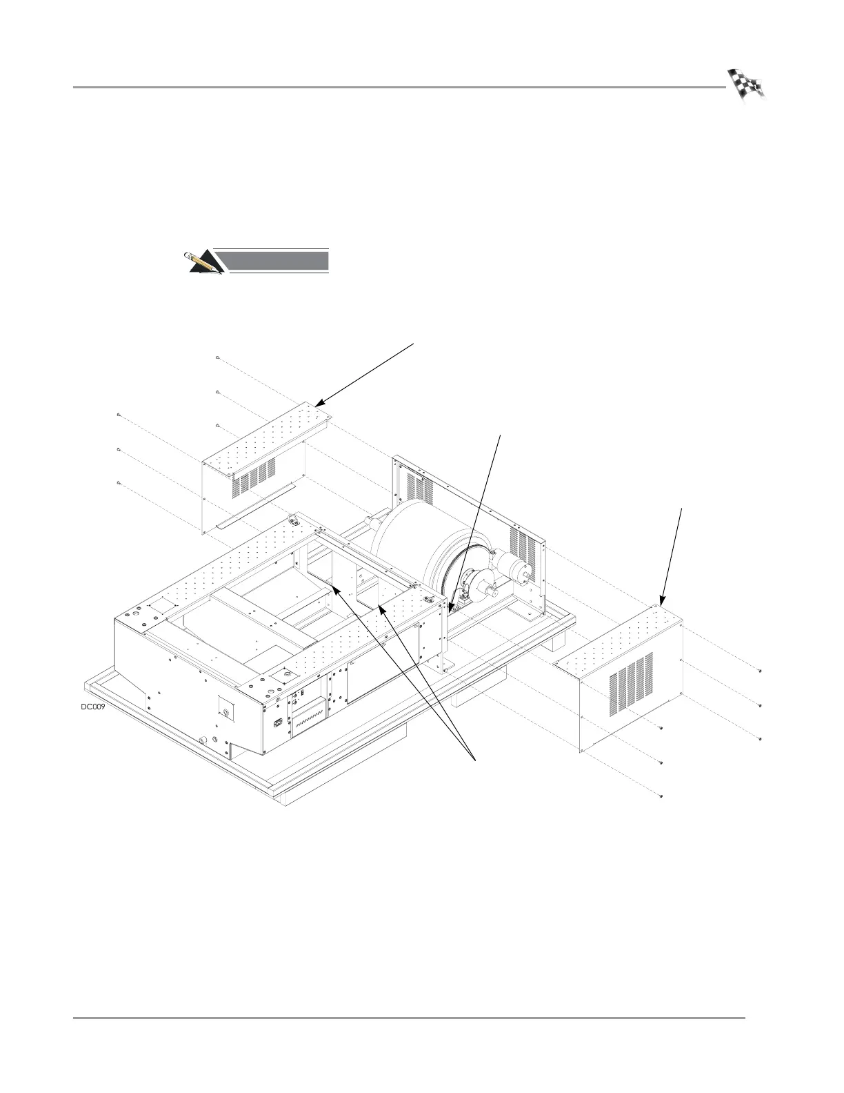
8 Remove the remaining six side screws securing each side drum cover to the dyno
and set aside. Remove the side drum covers and set aside.
Note: For future reference, note the three access holes in the drum bulkhead.
These access holes will be used to route cables when installing accessories once
the top cover is back on.
#
RECORD
Be sure you record the dynamometer number on the inside cover of this
manual.
Figure 2-4: Remove the Side Drum Covers
side drum cover
side drum cover
access holes in drum
bulkhead (only two
visible from this view)
dyno number stamped
on frame