Model 200i and 250i Motorcycle Dynamometer Installation Guide
CHAPTER 3
Air Brake
3-18
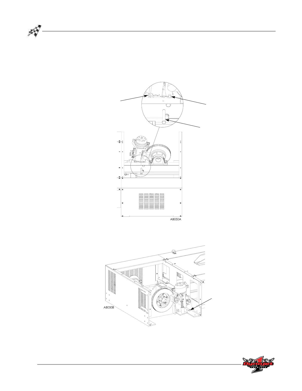
7 Push the bottom clevis pin towards the back of the assembly (drum side). You do
not need to remove the pin completely.
8 Remove the hairpin cotter from the top clevis pin located on the drum side of the
air brake assembly.
Figure 3-20: Remove the Bottom Pin and the Top Hairpin Cotter
9 Remove the top clevis pin.
Figure 3-21: Remove the Top Clevis Pin
bottom clevis pin
top hairpin cotter
top clevis pin
top clevis pin