xLogic SuperRelay User’s Manual
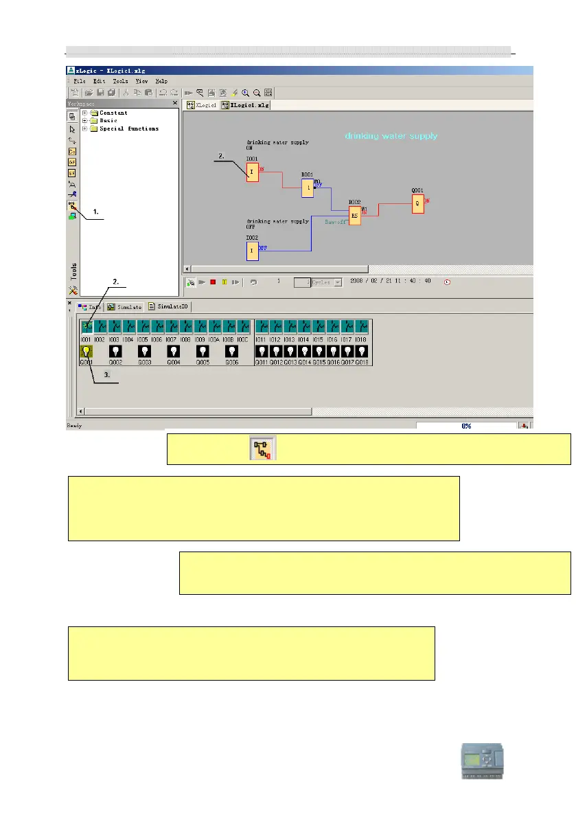
1. Select the tool if you want to test your program.
2. Once the simulation is activated, a symbol bar for operator control
and monitoring of inputs and outputs is called. A software switch is
used to simulate a power failure in order to test the retentive features
of the circuit behavior.
3. The input states can be modified by clicking the button in the
symbol bar (2) or clicking on the inputs in the display.
The connection sequence can be tracked by the change in color
of the connection lines from blue (low signal) to red (high signal).
This facilitates the detection and removal of errors significantly.