9 CANopen
9.2 System overview
DC1 variable frequency drive 12/13 MN04020003Z-EN www.eaton.com 153
9.2.5 Set CANopen user address
Every CANopen module needs a unique address (node ID) within the
CANopen structure. All node IDs must be unique within the entire bus
structure. A maximum of 127 addresses (1 to 127) can be assigned within a
CANopen structure.
Parameter P-36 is used to set the CANopen address in DC1 variable
frequency drives (value between 1 and 63).
9.2.6 Parameters that need to be configured
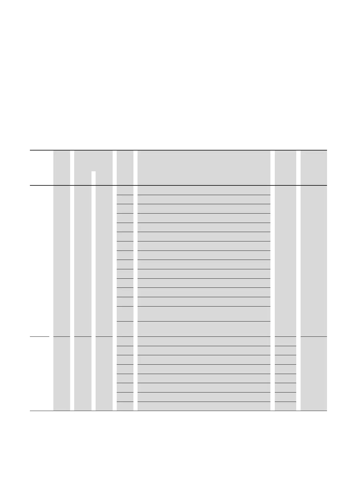
PNU ID Access right Value Description DS Value that
must be
configured
RUN ro/rw
P-12 140 – rw Control level 0 7.8
0 Control signal terminals
1 Keypad (FWD)
2 Keypad (FWD/REV)
3 Modbus (internal ramp times)
4 Modbus (internal ramp times)
5 PI controller with external actual value
6 PI controller with external actual value and totalized value of AI1
7 CANopen (internal ramp times)
8 CANopen (CANopen ramp times)
9 SmartWire-DT (SWD control command and setpoint value)
10 SmartWire-DT (SWD control command; internal setpoint value)
11 SmartWire-DT (SWD setpoint value; internal control command)
12 SmartWire-DT (control will depend on the configuration in the event
of a loss of communications; automatic switch to local control)
13 SmartWire-DT (SWD control command and setpoint value; in
addition, an enable signal via DI1 and an enable setpoint via DI2)
P-36
164 – rw Serial communication configuration
1 - 63 Variable frequency drive slave address 1
Modbus RTU baud rate 6
2 9.6 kBit/s
3 19.2 Kbit/s
4 38.4 kBit/s
5 57.6 kBit/s
6 115.2 kBit/s

 Loading...


