11 Annex
11.10 Expansion modules
DC1 variable frequency drive 12/13 MN04020003Z-EN www.eaton.com 203
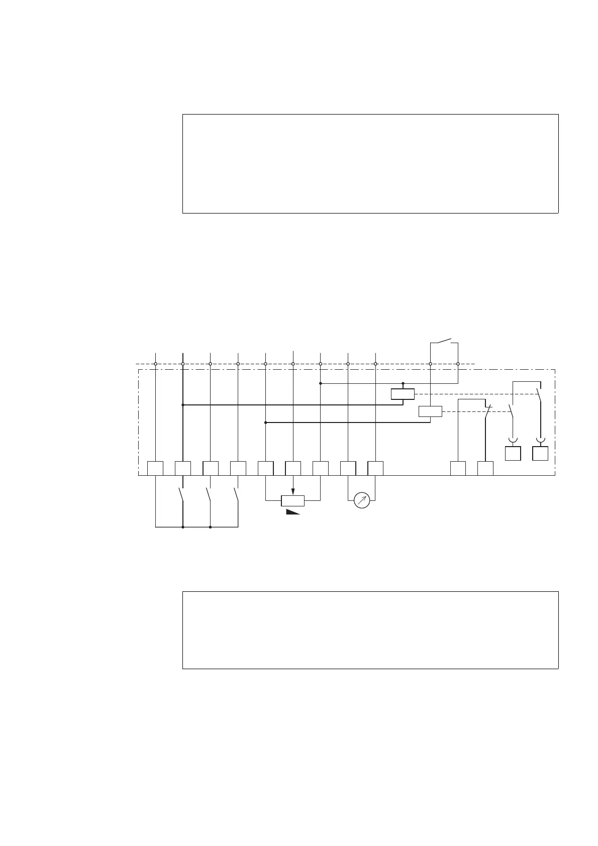
11.10.3.3 Block diagram
Figure 114: Block diagram DXC-EXT-2RO1AO
11.10.3.4 Parameter definition
DANGER
Dangerous voltage!
Expansion module DXC-EXT-2RO1AO must not be placed into
operation until all mounting and installation work has been
completed. Any other use will be considered to be an inappro-
priate use.
→
The control signal terminals on the DC1 variable frequency drive
are plug-in terminals. They can be screwed onto the expansion
module in order to cover the pins (protection against contact).
2
DI1
3
DI2
4
DI3
1
5
+10 V
< 20 mA
6 7
0 V
0 V
8 9 10 11
12 13
1DC1 2 3 4 5 6 8 9 10 11
P-18 = 1
RUN
7
AI
0 ... +10 V
A0
0 ... +10 V/
20 mA
+24 V, <100 mA
f-Soll
f-Out
K1
K2
250 V AC/220 V DC, 1 A
4.7 kΩ
+
FWD
NOTICE
Parameter P-25 must be set to a value between 0 and 7 and
function as a digital output.
If it is set to a value greater than 7, the K2 relay output will not
work properly.

 Loading...


