63
© 2017 Eaton. All rights reserved
2018.12.12
VCS/VMS Auxiliary Section Assembly and Installation | Service Procedures TRSM0940
Auxiliary Countershaft Assembly and Timing
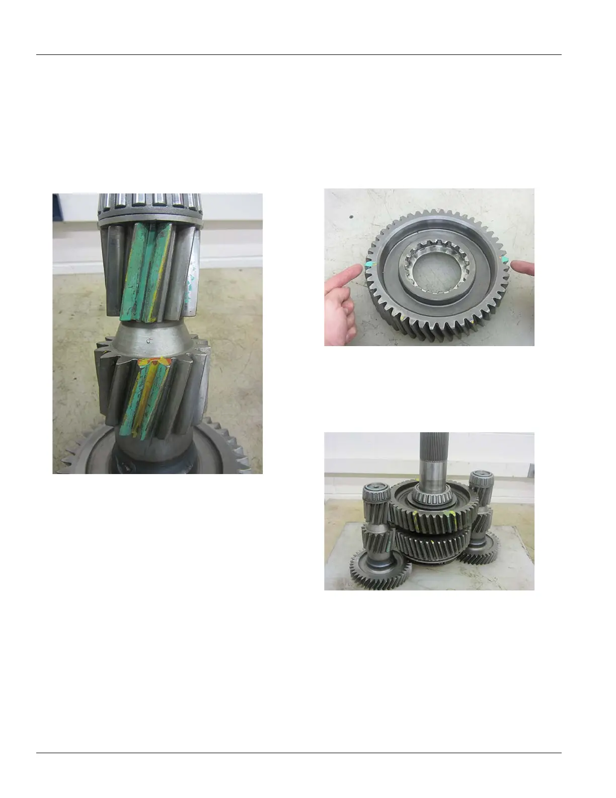
1. For timing purposes, identify and mark with a highly
visible paint pen the two (2) teeth on each countershaft
that are identified with a “0” on the shaft. Use a straight
edge to line up the marked teeth with the teeth on the
remaining two (2) countershaft gears. Paint these
teeth.
2. Position
the two Auxiliary Countershaft assemblies on
a clean flat surface. Position the shafts so that the
painted timing teeth are facing inward towards each
other.
Note: To ease
in the assembly and timing procedure.
Use a fixture similar to the one outlined at the begin-
ning of the section.
3. Install the
assembled Auxiliary Mainshaft Assembly
between the countershafts and match the timing
marks.
 Loading...