4 Functional description
4.1 Functional diagram
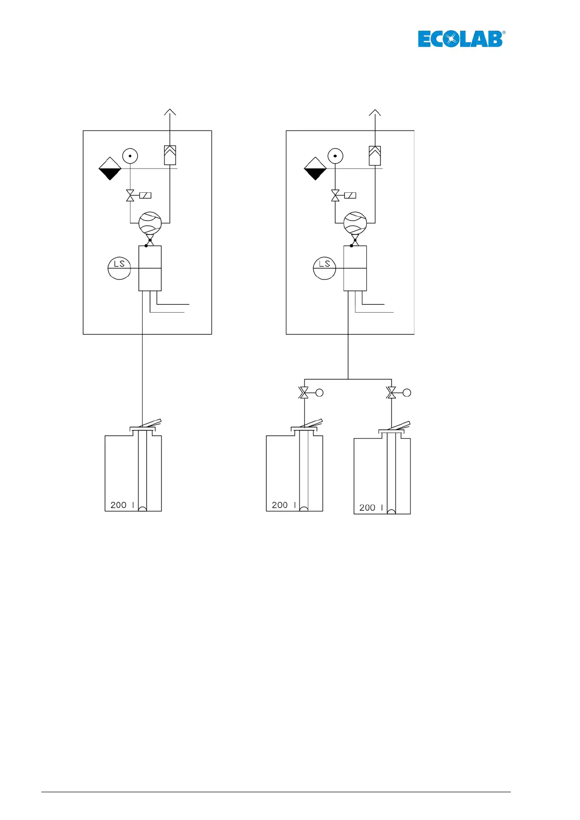
Fig. 1: Functional diagram
Connexx Basic or Connexx Switch systems are installed between the suction connection
of the metering pump(s), and the container suction pipe.
They take over the function of empty signal and provide venting for disinfection products
prone to outgassing
Ä
Chapter 2.3 ‘Suitable products’ on page 11.
Two product containers can be connected to the Connexx Switch.
After an empty signal of a container, a switch-over automatically happens to the other.
This switch-over function can be retrofitted in case of Connexx Basic with the help of a
valve sub-assembly
Ä
9 ‘Spare parts and accessories’ on page 41.
For operating the Connexx, apart from the 230 V 50/60 Hz power
supply,oil and condensate-free compressed air with 0.3 / 0.5 - 0.6 MPa (3 / 5 – 6 bar)
Ä
Chapter 4.2.3 ‘Compressed air supply and exhaust air connection’ on page 18 as well
as connection to an exhaust duct with at least DN20 are required.
Functional description
14Rev. 1-06.2018
 Loading...