4.5.3 Operation and Displays
The control unit has 4 LED displays for ON, empty signal LL1, empty signal LL2 and
collective fault signal (Quit). The master switch on the left side interrupts the power supply.
The push buttons LL1, LL2 and Quit help in acknowledging the empty and fault signal.
ON = Green, when connected to the mains and master switch ON
LL1 = Green, if container 1 is active blinking red, if container 1 empty
LL2 = Green, if container 2 is active blinking red, if container 2 empty (only in
case of Connexx Switch, otherwise not activated)
Quit = Red, if container is empty; in case of container switch-over: if
container 1 and 2 are empty
CAUTION!
Continuous red light in case of LL1, LL2 or QUIT after acknowledging), means
"short circuit or break in the solenoid vale outputs!"
LL1 = Pilot valve container 1, LL2 = Pilot valve container 2,
Quit = Solenoid valve (air). The equipment may not be used till the defect has
been rectified
Ä
Chapter 7 ‘Fault finding and rectification’ on page 37.
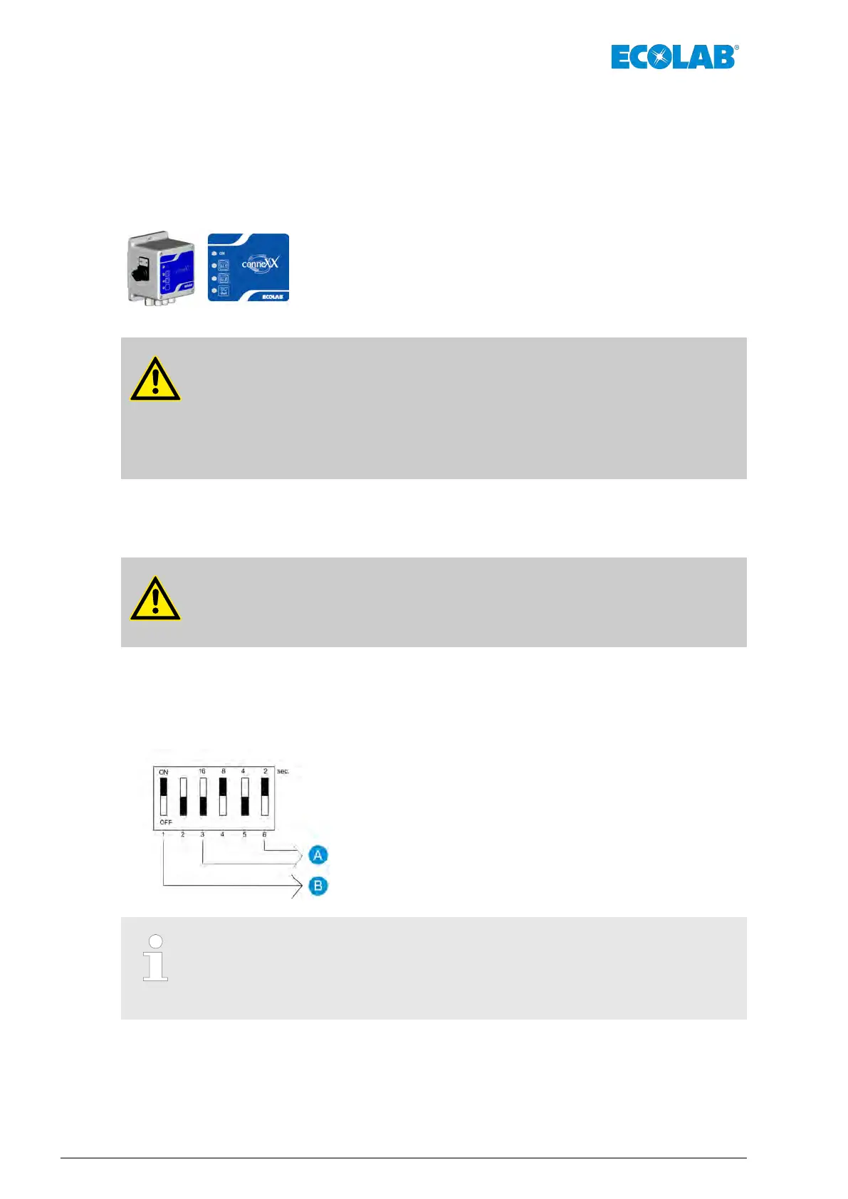
4.5.4 Adjusting elements
WARNING!
Switch off the control unit and disconnect it from the mains before opening the
cover
.
The automatic container switch-over as well as the suction time monitoring function
Ä
Chapter 4.3 ‘Suction hose vent and emptying of residue’ on page 20 can be adjusted
with the DIL switch on the board.
A = Suction time (0001=2 sec., 0010=4 sec., 0101=10 sec. to
1111=30 sec.)
B = Container switch-over (0 = inactive, 1 = active)
Switch 1 is adjusted by the manufacturer as per the equipment design. A
switch-over is required only in case of retrofitting of Connexx Basic with a
container switch-over or while replacing the control unit in case of Connexx
Switch.
Functional description
26Rev. 1-06.2018
 Loading...